Installation of Unit
Installation Manual 13
Connecting the Cable to Indoor Unit
• In order to protect cable, it should be inserted “Bushing Rubber”.
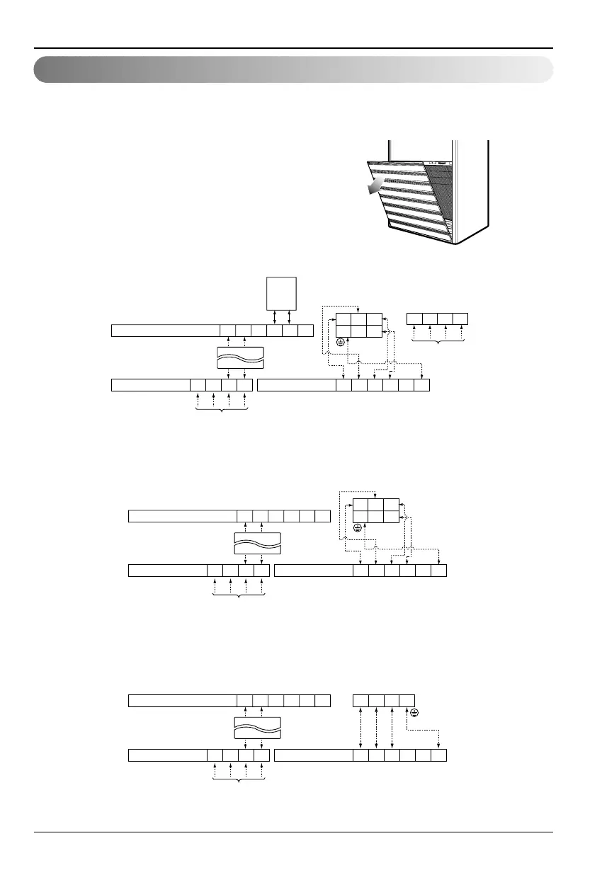
• The inside and outside connecting cable can be connected after opening the inlet grille.
1. Open the inlet grille manually.
2. Open the control cover with Driver(
⊕⊕
).
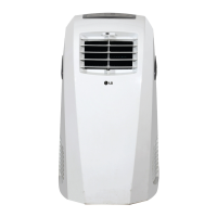
3. Connect the supplied cables to the connector in the control box. (LP-Z808FA0)
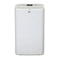
4. Connect the supplied cables to the connector in the control box. (LP-H808FA0)
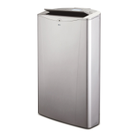
5. Connect the supplied cables to the connector in the control box. (LP-C80*F*0,LP-C100*F*0)
Where, *=8, 9, B *=A, E
Terminals on the indoor unit
CONNECT TO CONTACT "T", "N", OF
OUTDOOR TERMINAL BLOCK
MAGNETIC
SWITCH
123456
Terminals on the outdoor unit
Housing ASM
(Connect to Outdoor)
BR BRBL BL GN/YL
POWER INPUT
3P4W 380~415V Heater Power
POWER INPUT
3P4W 380~415V
1(L) 2(N) 3 4
12
3RSTN
654
5
6
Main Terminal on the outdoor unit
RSTN
Terminals on the indoor unit
CONNECT TO CONTACT "T", "N", OF
OUTDOOR TERMINAL BLOCK
123456
Terminals on the outdoor unit
Housing ASM
(Connect to Outdoor)
BR BRBL BL GN/YL
POWER INPUT
3P4W 380~415V
1(L) 2(N) 3 4
123
654
5 6
RSTN
Main Terminal on the outdoor unit
Terminals on the indoor unit
CONNECT TO CONTACT "T", "N", OF
OUTDOOR TERMINAL BLOCK
123456
Terminals on the outdoor unit
Housing ASM
(Connect to Outdoor)
BR BKBL GN/YL
POWER INPUT
3P4W 380~415V
1234
1234
5 6
RSTN
Main Terminal on the outdoor unit