Do you have a question about the LG LRFC25750ST and is the answer not in the manual?
Procedures for disassembling refrigerator and freezer doors.
Steps to remove and disassemble the fan and motor.
Instructions for removing the defrost control assembly.
Procedures for replacing refrigerator and freezer compartment lamps.
Steps to remove the refrigerator control box.
Instructions for removing and disconnecting the multi duct.
Explains the role, composition, and notes for handling the compressor.
Details the composition, role, and usage notes for the PTC starter.
Defines, explains the role, and provides a cross-section of the OLP.
Step-by-step instructions for removing the PTC cover.
Troubleshooting flowchart for compressor and electrical issues.
Troubleshooting steps for PTC starter and OLP issues.
Troubleshooting for issues with other electrical parts like fan motors.
A chart for diagnosing common refrigerator problems.
Details causes, states, and remarks for refrigeration cycle issues.
A flowchart for diagnosing problems within the sealed refrigeration system.
Explains the operational steps of the icemaker.
Details control methods for start, ice making, and harvest modes.
Describes the water fill and park positions for the icemaker.
Outlines the procedure and diagnosis for the icemaker function test.
Lists error codes and their meanings for the icemaker.
Explains basic functions like temperature settings and display modes.
Details the open door alarm feature and its timings.
Describes the buzzer sound produced when buttons are pressed.
Explains the defrosting cycle initiation and termination conditions.
Describes the sequence of electrical parts activation during initial power-on and test mode.
Explains the automatic diagnosis feature and lists error codes on the display.
Details how to operate and what to check during various test modes.
Overview of the Power Circuit and its voltage components.
Describes the circuit generating the base clock for the MICOM.
Explains how the reset circuit initializes functions and the MICOM.
Details load drive conditions, fan motor circuits, and open door detection.
Checks the conditions for buzzer activation for button presses and door alarms.
Explains how the open door detection circuit works and its checks.
Describes the circuit for reading refrigerator, freezer, and defrost sensor temperatures.
Details the damper circuit for regulating refrigerator temperature.
Explains the circuit for key presses and LED display illumination.
Provides resistance values for sensors at different temperatures.
Diagnoses and resolves problems related to the power source.
Identifies causes and solutions for poor cooling performance.
Troubleshoots situations where the unit is not cooling at all.
Addresses issues with incorrect freezer temperature settings.
Diagnoses and resolves problems related to the defrosting system.
Troubleshoots cases where the defrosting function is not working.
Diagram showing the layout of the main Printed Circuit Board.
Comprehensive list of replaceable parts with part numbers and descriptions.
Details the display PWB assembly and its associated parts.
Schematic diagram of the main Printed Circuit Board assembly.
Exploded view of the external case parts for identification.
Exploded view of the freezer compartment parts for identification.
Exploded view of the refrigerator compartment parts for identification.
Exploded view of the door components for identification.
Exploded view of the ice maker and related parts for identification.
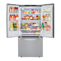
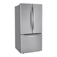
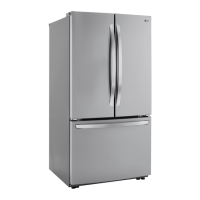
| Type | French Door |
|---|---|
| Total Capacity | 25.0 cu. ft. |
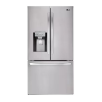
| Ice Maker | Yes |
| Water Dispenser | Yes |
| Color | Stainless Steel |
| Energy Star Certified | Yes |
| Width | 35.75 inches |
| Height | 69 3/4" |