Do you have a question about the LG LRG4111ST and is the answer not in the manual?
Safety guidelines for servicing the appliance, including warnings about gas and electrical hazards.
Procedures for testing various components like motor, sensor, igniters, and valves.
Steps to prepare the appliance before gas conversion.
Instructions for converting the gas pressure regulator.
Electrical schematic illustrating the appliance's wiring connections.
Identification of Main, Touch, NFC, and Buzzer PCBs.
Step-by-step guide to enter and use the Service Test Mode.
Summary of basic checks for common symptoms in SVC Test Mode.
Procedure to check and understand appliance error codes.
Detailed steps to diagnose and resolve appliance malfunctions.
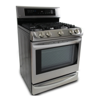
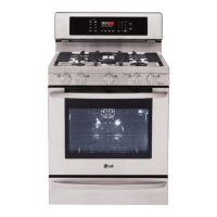
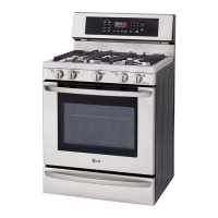
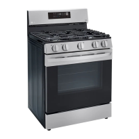
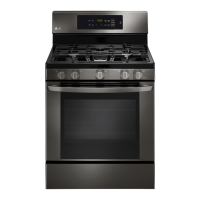
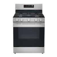
Overall dimensions, installation, control features, and display types.
Cooktop burner power, oven capacity, and BTU ratings.
Appliance external dimensions, weight, and electrical specifications.
Location of the model and serial number rating label for parts ordering.
Explanation of basic oven modes like Bake, Broil, and Convection.
Description of buttons for Bake, Roast, Warm, Pizza, and Easy Clean functions.
Description of buttons for Light, Clock, Settings, Cook Time, and Start Time.
How to turn on and control surface burners, including notes on sparking.
Procedures for setting the appliance's clock and timer.
How to use Warm, Proof, Lockout, Easy Clean, and adjust beeper/units.
Procedures for setting timed and delayed cooking for Bake, Conv. Bake, and Roast.
Diagram showing the location of major internal components within the range.
Step-by-step instructions for removing the back panel, control cover, and glass touch assembly.
Instructions for removing the spark module and power control board (PCB).
Information on replacing signal harnesses connecting various PCBs.
Procedure for removing the cooktop plate.
Steps to remove cooktop parts including the gas valve.
Steps to remove the ignition switch and electrode (spark plug).
Procedure for removing the oven door switch.
Instructions for removing the broil burner assembly and igniter.
Steps to remove the convection fan blade and motor assembly.
Procedure for removing the oven light and socket assembly.
Steps to remove the oven temperature sensor.
Instructions for removing and replacing the storage drawer.
Procedure for removing and replacing the oven door.
Steps to remove the oven door handle and glass components.
Procedure for removing the oven door hinge hanger assembly.
Steps to remove and replace the oven door gasket.
Procedure for removing one of the appliance's side panels.
Instructions for removing the oven valve (safety valve) and gas pressure regulator.
Test procedures and expected results for the convection motor.
Test procedures for oven sensor and door switch.
Test procedures for oven lamp and Igniter Type-1.
Test procedures for Igniter Type-2 and oven safety valve.
Test procedures for the ignition switch.
Steps to prepare the appliance before gas conversion.
Instructions for converting the gas pressure regulator.
Steps to convert surface burners to LP gas using orifice spuds.
Diagram showing LP orifice locations for each burner.
Specifications for natural gas orifices including BTU rate and orifice code.
Diagram showing natural gas orifice locations for each burner.
Steps to convert bake burner orifices for LP gas.
Steps to convert broil burner orifices for LP gas.
Adjusting air shutter and checking flame quality for LP gas.
Procedure to adjust the low flame setting for surface burners.
Electrical schematic illustrating the appliance's wiring connections.
Identification of Main, Touch, NFC, and Buzzer PCBs.
Detailed view and connector labels for the Main PCB.
Detailed view of the Touch PCB.
Detailed view of the NFC PCB.
Detailed view of the Buzzer PCB.
Step-by-step guide to enter and use the Service Test Mode.
Table showing the sequence of relay operations in SVC Test Mode.
Summary of basic checks for common symptoms in SVC Test Mode.
Procedure to display and check error codes on the appliance.
Table listing error codes, their descriptions, and check points.
Steps to troubleshoot power failure and no display symptoms.
Flowchart for diagnosing power failure and no display issues.
Steps to troubleshoot 'No heating' and 'F9' error codes.
Steps to troubleshoot heating/sensor issues by checking wiring, igniter, and sensor.
Detailed steps for diagnosing F9 error, checking connectors and igniters.
Checking the resistance of Norton and SIC igniters.
Checking thermistor resistance and using test mode for F9 error.
Steps to troubleshoot sensing fail errors by checking wiring and sensor.
Flowchart for diagnosing sensing fail errors (F1, F2) by checking connectors and thermistor.
Using test mode to check thermistor value for potential Main PCB replacement.
Steps to troubleshoot Oven Hot (F6) by checking relay and sensor resistance.
Checking oven sensor resistance for Oven Hot (F6) error.
Checking thermistor and igniter relay resistance for F6 error.
Checking DLB relay and thermistor value in test mode for F6 error.
Steps to troubleshoot convection fan not working (F7) by checking relay and motor.
Checking the resistance of the fan motor (high and low speeds).
Measuring the resistance of fan motor relays (RY61, RY62).
Checking convection fan connectors and harnesses for loose connections.
Steps to troubleshoot key input issues and F3 error by checking wiring.
Flowchart for F3 error, checking Touch PCB to Main PCB connection.
Overview of model and product codes, and introduction to parts diagrams.
Exploded view of the appliance's door components.
Exploded view of the appliance's control panel and related parts.
Exploded view of the appliance's cooktop components.
Exploded view of the appliance's drawer and slide components.
Exploded view of the appliance's oven cavity and internal parts.
| Type | Freestanding |
|---|---|
| Color | Stainless Steel |
| Oven Capacity | 5.4 cu. ft. |
| Number of Burners | 5 |
| Burner Type | Sealed |
| Self-Cleaning | Yes |
| Convection Oven | Yes |
| Wi-Fi Connectivity | No |
| Fuel Type | Gas |
| Width | 30 in |