J
Justin RossAug 8, 2025
Why does my LG LS-Q096BEL Air Conditioner have refrigerant leakage?
- DDanielle MontesAug 9, 2025
Refrigerant leakage in your LG Air Conditioner can occur due to a clog in the refrigeration cycle or a defective compressor.
Why does my LG LS-Q096BEL Air Conditioner have refrigerant leakage?
Refrigerant leakage in your LG Air Conditioner can occur due to a clog in the refrigeration cycle or a defective compressor.
Why is my LG LS-Q096BEL leaking refrigerant?
Refrigerant leakage in your LG Air Conditioner can occur due to a clog in the refrigeration cycle or a defective compressor.
What causes high suction pressure and high temperature in LG LS-Q096BEL?
High suction pressure and high temperature in your LG Air Conditioner can be caused by a defective compressor or a defective 4-way reverse valve. In both cases, the current is likely to be low.
Why is suction pressure higher and temperature high in my LG Air Conditioner?
If the suction pressure and temperature are both high in your LG Air Conditioner, it could be due to a defective compressor or a defective 4-way reverse valve.
Explains the structure and meaning of model name components introduced in 2002.
Provides a breakdown of codes used for chassis, capacity, and features.
Covers basic operations like ON/OFF, temperature control, and fan speed.
Describes airflow direction, Chaos Logic, and Plasma purification.
Explains core buttons like Start/Stop, Mode, and Temperature settings.
Details timer functions, sleep mode, and airflow direction controls.
Lists cooling capacity, heating capacity, and EER/COP values for various models.
Details power source, noise levels, dimensions, and weight.
Provides detailed measurements for the indoor unit and installation plate.
Lists dimensions for outdoor units based on capacity and type.
Illustrates the refrigeration cycle for cooling-only units.
Shows the refrigeration cycle for units capable of both cooling and heating.
Provides wiring schematics for indoor unit components.
Details the wiring connections for outdoor units.
Explains display indicators and core modes like Cooling and Dehumidification.
Details heating operations, defrost mechanisms, and Fuzzy logic.
Explains the Fuzzy control logic for cooling, heating, and dehumidification.
Details Fuzzy operations for dehumidification and heating.
Covers the Jet Cool mode and procedures for forced operation without a remote.
Explains auto-restart functionality and air cleaner operation.
Describes the meaning of display indicators for heating and cooling models.
Details the self-diagnosis function and error code 1 interpretation.
Specifies requirements for indoor and outdoor unit installation locations.
Outlines maximum piping length and elevation differences for installation.
Details the steps for correct pipe flaring to prevent refrigerant leaks.
Covers connecting indoor piping, drain hose, and insulation.
Describes how to connect pipes to the outdoor unit and secure them.
Explains how to manage and secure the pipes at the rear of the unit.
Guides on connecting cables between units and wire specifications.
Details power source requirements and circuit breaker installation.
Explains how to check the indoor unit's drainage and form the drain piping.
Covers forming piping, securing it, and installing traps to prevent water entry.
Details how to check performance after installation, including temperature and pressure.
Explains the process of collecting refrigerant for relocation or servicing.
Lists and describes the functions of each button on the remote control.
Explains how to select different operating modes like Cooling, Auto, and Heating.
Provides a general warning and initial steps for disassembling the indoor unit.
Details the process for removing specific parts like the control box, grille, and evaporator.
A table detailing shaft positions and service port operations for various tasks.
Explains procedures for air purging and pumping down the refrigerant circuit.
Describes air purging steps during re-installation.
Covers balancing refrigerant and the evacuation process.
Details how to connect and charge the system with refrigerant.
Analyzes issues based on temperature differences and operating current.
Guides on checking cycle pressure for troubleshooting.
Steps to diagnose issues when the unit shows no operation.
Diagnosing problems when the remote control is unresponsive.
Diagnosing issues with compressor or fan motor operation.
Troubleshooting steps for indoor fan and vertical louver problems.
Details the AC components on the main PCB, showing top and bottom views.
Details the DC components on the main PCB, showing top and bottom views.
Provides the overall schematic diagram, showing DC and AC components.
Details schematics specific to Cooling Models (LED and HVB types).
Provides a visual breakdown and parts list for the indoor unit.
Provides a visual breakdown and parts list for the outdoor unit.
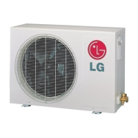
| Brand | LG |
|---|---|
| Model | LS-Q096BEL |
| Category | Air Conditioner |
| Language | English |