M
michaelbrownAug 2, 2025
Why does my LG Air Conditioner have refrigerant leakage?
- DDebra HowardAug 2, 2025
Refrigerant leakage in your LG Air Conditioner can occur due to a clog in the refrigeration cycle or a defective compressor.
Why does my LG Air Conditioner have refrigerant leakage?
Refrigerant leakage in your LG Air Conditioner can occur due to a clog in the refrigeration cycle or a defective compressor.
Controls the air conditioner's operation by starting and stopping it.
Allows selection of the air conditioner's operating mode.
Used to adjust the desired room temperature.
Selects fan speed in four steps: low, medium, high, and CHAOS.
Starts or stops rapid cooling operation with super high fan speed.
Activates the Sleep Mode Auto operation for comfort.
Starts or stops the plasma purification function.
Illustrates the refrigeration cycle for cooling-only air conditioner models.
Shows the refrigeration cycle for models capable of both cooling and heating.
Electrical wiring schematics for various indoor unit models.
Electrical wiring schematics for outdoor units.
Explains indicators and operations for Cooling Only models.
Explains indicators and operations for Heat Pump models.
Details compressor and fan behavior during cooling operation based on temperature.
Explains compressor and fan behavior during heating operation.
Outlines the process for defrosting the outdoor unit's evaporator during heating.
Fuzzy logic control for Cooling Only models based on temperature.
Fuzzy logic control for Heat Pump models.
How to manually select indoor fan airflow speed using the remote.
Setting the timer for the unit to start operating automatically.
Provides rapid cooling by operating the fan at super-high speed for 30 minutes.
Allows basic operation using the power button when the remote is unavailable.
Performs a short diagnostic run to check basic functionality.
Restores previous operating conditions after a power failure.
Details the operation of the plasma air cleaner function.
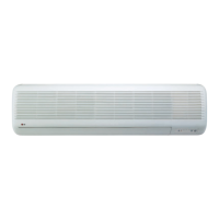
Describes the function of various indicators and displays for heating and cooling models.
Explains error codes and corresponding checks for indoor unit operation LED.
Guidelines for selecting optimal locations for indoor and outdoor units.
Specifies allowed piping lengths and elevation differences for reliable system performance.
Instructions for cutting refrigerant pipes and electrical cables to the correct length.
Procedure for safely removing burrs from pipe ends to prevent contamination.
Specific instructions and dimensions for performing proper flaring.
Steps for preparing indoor unit piping and drain hose for wall installation.
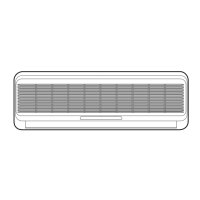
Guidance on how to hang and secure the indoor unit onto the installation plate.
Instructions for connecting the electrical cable to the indoor unit's control board.
Instructions for connecting the electrical cable to the outdoor unit's control board.
Procedure to verify proper water flow through the drain hose.
Instructions for shaping and securing refrigerant piping and drain hoses.
Steps for operating the unit and checking refrigerant charge and air temperature differences.
Method for collecting refrigerant into the outdoor unit for servicing or relocation.
Steps to remove the front grille from the indoor unit chassis.
Procedure for safely removing the control box assembly.
Steps for removing the evaporator assembly, noting screw locations.
Steps to detach the cross-flow fan from the fan motor.
Description and operation of the 2-way valve used on the liquid side.
Description and operation of the 3-way valve used on the gas side.
Procedure for removing air from the system during installation to ensure proper operation.
Methods for detecting refrigerant leaks at connections and valve stems.
Analyzing intake/discharge air differences and operating current for troubleshooting.
Checking suction pressure and temperature against normal values for fault diagnosis.
Troubleshooting steps for a unit that does not operate.
Procedures for checking the main PCB for operational issues.
Top and bottom views of the AC part of the main Printed Wiring Board.
Top and bottom views of the DC part of the main Printed Wiring Board.
Electrical schematic diagram for cooling models.
Electrical schematic for models with HVB/Plasma functionality.
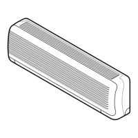
Detailed exploded view of the indoor unit components.
Exploded view illustrating the parts of the outdoor unit.
| Power Supply | 220-240V, 50Hz |
|---|---|
| Type | Split |
| Cooling Capacity | 18000 BTU/hr |
| Outdoor Unit Dimensions (W x H x D) | 840 x 540 x 320 mm |
| Noise Level (Indoor) | 42 dB |
| Operating Temperature (Cooling) | 18°C to 43°C |