C
Colleen TranAug 2, 2025
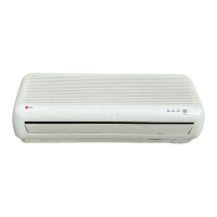
Why does my LG LS-T246AAL have refrigerant leakage?
- DDonna MullinsAug 2, 2025
Refrigerant leakage in your LG Air Conditioner can occur due to a clog in the refrigeration cycle or a defective compressor.
Why does my LG LS-T246AAL have refrigerant leakage?
Refrigerant leakage in your LG Air Conditioner can occur due to a clog in the refrigeration cycle or a defective compressor.
Defines the 'LS' prefix as LG Split Type Airconditioner.
Identifies chassis types, e.g., 'S R Chassis'.
Explains capacity coding, e.g., '09' for 9,000 Btu/h.
Details electric voltage and frequency codes.
Explains the coding for various functions and features in serial numbers.
Details codes for refrigerant types and modes.
Defines brand codes like 'L' for LG Brand.
Codes for manufacturing location and refrigerant type.
Identifies 'S' as Split Type Air Conditioner.
Codes for cooling-only, heat pump, and inverter types.
Explains capacity coding, e.g., '09' for 9,000 Btu/h.
Details electric voltage, frequency, and phase codes.
Identifies chassis types, e.g., 'LSP' for SP Chassis.
Defines codes for color and appearance.
Lists codes for various operational functions and features.
Details LG Model Development Serial Number coding.
Describes remote control operation start/stop.
Explains the room temperature sensor (Thermistor).
How the unit maintains set temperature.
Delayed indoor fan start for 5 sec.
Prevents restarting for 3 minutes.
Lists fan speeds: High, Med, Low, CHAOS, JET COOL.
Explains LED indicators for operation status.
Intermittent fan operation at low speed.
Auto fan speed and unit stop after set hours.
Irregular fan operation and speed variation.
Automatic or manual louver adjustment.
Explains the PLASMA function's operation.
Indoor/outdoor fan stops during defrost.
Indoor fan stops until evaporator reaches 28°C.
Button to start and stop the unit.
Selects various operating modes.
Adjusts the desired room temperature.
Sets fan speed to Low, Med, High, CHAOS.
Activates rapid cooling with super high fan speed.
Controls louver movement for airflow direction.
Sets operation start and stop times.
Adjusts the unit's clock time.
Sets or cancels timer operations.
Activates automatic sleep mode adjustments.
Circulates air without active cooling/heating.
Displays the current room temperature.
Activates or deactivates the plasma purification function.
Resets time settings or after battery replacement.
Adjusts horizontal airflow direction.
Circulates air without cooling or heating.
Used to access secondary functions on buttons.
Details model names and their associated features.
Specifies cooling and heating capacity in Btu/h.
Indicates moisture removal rate in liters/hour.
Details voltage, frequency, and phase requirements.
Airflow volume in m³/min for indoor and outdoor units.
Sound pressure level in dB(A) for indoor/outdoor units.
Electrical input power in Watts for cooling/heating.
Operating current in Amps for cooling/heating.
Energy Efficiency Ratio and Coefficient of Performance.
Motor power rating in Watts for indoor/outdoor units.
Physical dimensions in mm for indoor/outdoor units.
Weight of indoor/outdoor units in kg.
Type and quantity of refrigerant used.
Indicates if Up/Down control is available.
Specifies the type of remote control used.
Size of liquid and gas service valves in inches.
Indicates availability of sleep mode.
Indicates the presence of a drain hose.
Specifications for the connecting cable.
Specifications for the power cord.
Width, Height, and Depth of the indoor unit.
Shows the installation plate diagram.
Explains various dimensions of the outdoor unit.
Diagram showing the refrigeration cycle for cooling-only units.
Diagram showing the cycle for cooling and heating units.
Wiring diagrams for indoor units like LS-T212CAG and LS-C266TGF0.
Wiring diagrams for various outdoor unit models.
Explains indicators and functions of the main unit display.
Details operation, sleep, timer, and compressor indicators for C/O models.
Details operation, sleep, timer, and defrost indicators for H/P models.
Explains compressor and fan behavior based on temperature.
Details temperature settings for dehumidification.
Covers compressor/fan behavior in dehumidification mode.
Explains compressor/fan behavior in heating mode.
Details the defrost control mechanism and conditions.
Explains Fuzzy logic for cooling-only models.
Explains Fuzzy logic for heat pump models.
Details Fuzzy logic for cooling operations.
Details Fuzzy logic for dehumidification.
Details Fuzzy logic for heating operations.
How to select fan speed via remote.
How to set and use the on-timer.
How to set and use the off-timer.
Details sleep timer modes and effects.
Explains the automatic louver swing function.
Describes the random fan speed variation mode.
Details the Jet Cool function for C/O and H/P models.
Operation without remote control.
Procedure for testing the unit's functions.
Unit's behavior after power failure.
How the air cleaner/plasma function works.
Operation based on main unit slide switch.
Mechanism to prevent evaporator frosting.
Explains buzzer sounds for different operations.
Details indicators for heating mode.
Details indicators for cooling mode.
Explains error code 1 for thermistor issues.
Criteria for selecting the indoor unit installation site.
Guidelines for piping length and height differences.
Required clearances for indoor unit installation.
Guidelines for installing the outdoor unit.
Cautions for outdoor unit placement and mounting.
Steps for mounting the installation plate securely.
Procedure for drilling the piping hole.
Table of distances for plate mounting.
Detailed steps for cutting, burr removal, and flaring pipes.
Standards for pipe cutting and flaring dimensions.
How to inspect the quality of flaring work.
Steps for connecting piping and drain hose to the indoor unit.
How to mount the indoor unit onto the installation plate.
Tightening flare nuts and wrapping pipes for indoor unit.
How to wrap insulation material around connecting portions.
Routing pipes and hoses for left rear installation.
More steps for connecting pipes and drain hose.
Hanging the indoor unit and securing it.
Wrapping insulation and pipes for indoor unit.
Rerouting pipes and hoses across the back of the chassis.
Setting the tubing holder to the chassis.
Steps for connecting pipes to the outdoor unit.
Connecting the cable to the indoor unit's control board.
Specifications for power cords and connecting cables.
Requirements for main power source and circuit breaker.
Connecting the cable to the outdoor unit's control board.
Required circuit breaker ratings for outdoor units.
Important cautions for wiring installation and power supply.
Steps to remove the front panel for access.
How to verify proper water drainage from the evaporator.
Proper installation of the drain hose to ensure flow.
How to form piping when outdoor unit is below indoor unit.
How to form piping when outdoor unit is above indoor unit.
Verify tubing, wiring, and valve connections.
How to insert batteries into the remote control.
Securing the outdoor unit to its mounting base.
Measuring pressures and temperatures for performance check.
Typical gas side pressure for optimal conditions.
How to collect refrigerant for servicing or relocation.
Button to start and stop the unit.
Selects various operating modes.
Adjusts the desired room temperature.
Sets fan speed to Low, Med, High, CHAOS.
Activates rapid cooling with super high fan speed.
Controls louver movement for airflow direction.
Sets operation start and stop times.
Adjusts the unit's clock time.
Sets or cancels timer operations.
Activates automatic sleep mode adjustments.
Circulates air without active cooling/heating.
Displays the current room temperature.
Activates or deactivates the plasma purification function.
Resets time settings or after battery replacement.
Adjusts horizontal airflow direction.
Used to access secondary functions on buttons.
Emphasizes disconnecting power before checks.
Steps to remove the front grille from the chassis.
How to detach wires before removing the control box.
Steps to remove the main control box.
How to unhook and remove the discharge grille.
Steps to remove the evaporator assembly.
Warning to not damage the caution label during repair.
How to unhook the evaporator from the chassis.
Steps to remove the motor cover.
How to loosen and remove the cross-flow fan.
Illustration and function of the 2-way valve.
Illustration and function of the 3-way valve.
Table showing shaft positions for various operations.
Lists tools needed for air purging.
Explains why purging air is critical for performance.
Detailed steps for purging air from the system.
Checking for leaks after air purging.
Measures to take if gas leakage is found.
Diagram illustrating the pumping down process.
Detailed steps to collect refrigerant.
Diagram for air purging during re-installation.
Steps for air purging after re-installation.
Warning against refrigerant leakage during purging.
Diagram for balancing refrigerant in the system.
Steps to balance refrigerant levels.
Diagram illustrating the evacuation process.
Detailed steps for evacuating the system.
Notes on maintaining vacuum pump oil.
Diagram for charging refrigerant into the system.
Detailed steps for charging refrigerant.
Cautionary notes on charging liquid refrigerant.
Analyzes issues based on intake/discharge air temp difference.
Analyzes issues based on operating current.
Guides troubleshooting based on suction pressure and temperature.
Explains how humidity affects temperature difference.
Notes on normal suction pressure and measurement.
Troubleshooting steps for a completely non-operational unit.
Checks power voltage, connections, and PWB.
Checks SMPS, IC outputs, and soldering on the main PCB.
Troubleshooting steps when the remote control is unresponsive.
Checks connecting circuits and display PWB.
Checks the receiver assembly and related circuits.
Troubleshooting steps when compressor/fan won't start.
Verifies indoor temperature sensor and connectors.
Checks the compressor relay circuit and voltages.
Troubleshooting steps for a non-operating indoor fan.
Checks motor connection, fan motor, and fuse.
Checks Micom pins, TRIAC, and TRIAC operation.
Troubleshooting steps for louvers not moving.
Checks louver gearing and torque.
Checks connector, soldering, and voltage for louvers.
Troubleshooting steps when heating mode fails.
Checks intake/pipe sensors and related circuits.
Verifies DC voltages for relays on the PWB.
Checks wiring diagram, components, and connections for outdoor unit.
Diagram of the AC part of the main PWB, top view.
Diagram of the AC part of the main PWB, bottom view.
Wiring diagram for the cooling model PWB.
Wiring diagram for the heat pump model PWB.
Diagram of the DC part of the main PWB, top view.
Diagram of the DC part of the main PWB, bottom view.
Diagrams for display assembly 6871A20194.
Diagrams for display assembly 6871A30009.
Diagrams for display assembly 6871A20227.
Diagrams for display assembly 6871A20391.
Diagrams for display assembly 6871A20476.
Electrical schematic for the cooling model with LED indicators.
Electrical schematic for cooling model with HVB (Plasma) type.
Exploded view of the main indoor unit parts.
Exploded view showing parts specific to the Plasma model.
Exploded view of the front section of the indoor unit.
Exploded view of the rear section of the indoor unit.
Exploded view showing Type B indoor unit parts.
Exploded view of Type B indoor unit front section.
Exploded view of Type B indoor unit rear section.
Exploded view of other Type B indoor unit components.
Exploded view of top and rear outdoor unit parts.
Exploded view of base and fan assembly.
Exploded view of electrical and mounting parts.
More views of top and rear outdoor unit parts.
More views of base and fan assembly.
More views of electrical and mounting parts.
Additional exploded views of top/rear outdoor unit parts.
Additional exploded views of base/fan assembly.
Additional exploded views of electrical/mounting parts.
Final exploded views of top/rear outdoor unit parts.
Final exploded views of base/fan assembly.
Final exploded views of electrical/mounting parts.
Exploded views showing specific part numbers.
Further exploded views with specific part callouts.
| EER | 10.5 |
|---|---|
| Energy Efficiency Ratio (EER) | 10.5 |
| Voltage | 220-240V |
| Phase | 1 |
| Fan Speeds | 3 |
| Filter Type | Washable |
| Type | Split Air Conditioner |
| Cooling Capacity | 24, 000 BTU/h |