21
General Installation Guidelines
Due to our policy of continuous product innovation, some specifications may change without notification.
©LG Electronics U.S.A., Inc., Englewood Cliffs, NJ. All rights reserved. “LG” is a registered trademark of LG Corp.
GENERAL INSTALLATION GUIDELINES
Installation Plate
39-9/32 (998)
2-23/32 (69)
14-11/16 (373)
5-13/32 (137)
2-3/32 (53)
13-19/32 (345)
Ø2-9/16 (65)
3-9/32 (83)
Unit Outline
1-1/16 (27)
5-29/32 (150)
4-17/32 (115)
Ø2-9/16 (65)
3-9/32 (83)
5-9/32 (134)
1-1/16 (27)
2-3/32 (53)
11-13/16 (300)
5-29/32 (150)
7-13/32 (188)
Installation Plate
Chassis
Hook
Type "A" Screws
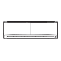
Figure 17: Mega 18 and 24K Wall Mount Indoor Unit Installation
Plate.
Figure 18: Mega 18 and 24K Wall Mount Indoor Unit Installation Plate Dimen-
sions.
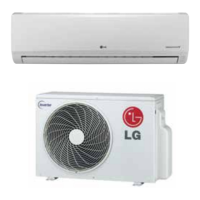
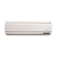
Figure 19: Indoor Unit with the Bottom Cover On (Bottom View; Appear-
ances Will Vary Depending on Indoor Unit Model).
Figure 20: Steps to Removing the
Bottom Cover.
To access the indoor unit piping port connections,
terminal block, and to make the indoor unit installation
procedure easier, it is recommended that the bottom
cover be removed first.
1. Unsnap the bottom cover at its top left and right
sides (Location 1).
2. Unsnap each of the three (3) or four (4) small
C-hooks located in the middle of the bottom cover
(Location 2). Number of C-hooks present depends
on model of indoor unit.
3. Lift the three (3) to four (4) hinges on the bottom
cover up and out of the channels molded to the
left, right, and middle of the indoor unit (Location
3). Number of hinges present depends on model
of indoor unit.
4. Set aside the bottom cover to re-install after all
procedures are complete.
3
3
3
Removing the Indoor Unit Bottom Cover (Mega HEV2 Indoor Units Only)
Figure 21: Removing the Bottom Cover
(Appearances Will Vary Depending on
Indoor Unit Model).
Indoor Unit Mounting
 Loading...