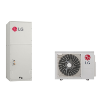
Refrigeration Cycle Diagram
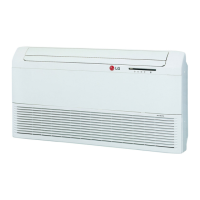
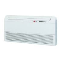
• LV-B1861CL
• LV-B1864CL
• LV-B2461CL
• LV-B2464CL
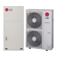
Pipe size(Diameter:) Piping length(m) Elevation(m)
MODEL
Gas Liquid Rated Max Rated Max
LV-B1861CL 1/2" 1/4" 5 15 5 8
LV-B1864CL 1/2" 1/4" 5 15 5 8
LV-B2461CL 5/8" 1/4" 5 20 5 8
LV-B2464CL 5/8" 1/4" 5 20 5 8
–9–
For installation over rated distance, 30g of refrigerant should be added for each meter.
ex) When installed at a distance of 15m, 300g of refrigerant should be added.
(15-5) x 30g = 300g
 Loading...