Do you have a question about the LG LV100CE and is the answer not in the manual?
| Type | Split System |
|---|---|
| Energy Efficiency Ratio (EER) | 11.0 |
| Power Supply | 220-240V, 50Hz |
| Refrigerant | R410A |
| Noise Level (Outdoor) | 50 dB(A) |
| Operating Temperature (Cooling) | 18°C to 43°C |
Procedure for checking the electrical grounding of the electronic type unit.
Procedure for checking the electrical grounding of the mechanical type unit.
Important safety instructions for installing the air conditioner unit.
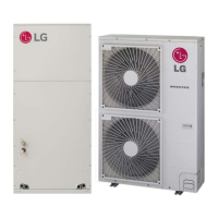
Technical specifications for LC and HBLG series room air conditioners.
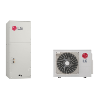
Technical specifications for LV series room air conditioners.
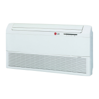
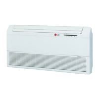
Key features of the LG room air conditioner.
Description of controls for the mechanical type model.
Description of controls for the electronic type model and remote.
Step-by-step guide for disassembling mechanical components.
Steps for removing air guide, turbo fan, and fan.
Procedure for removing overload protector and compressor.
Instructions for disassembling electrical components like capacitors, cords, and switches.
Steps for disassembling motor and refrigerating cycle parts (condenser, evaporator).
Procedure for removing capillary tube and refrigerant charging/handling.
Guidance on securely installing the air conditioner unit.
Key checks before startup and proper water drainage setup.
Specifications for windows and contents of installation kits.
Detailed steps for installing the unit in a horizontal sliding window.
Specific procedures for installing the unit in a casement window.
Diagram of the piping system and explanation of the refrigeration cycle.
Troubleshooting steps for ineffective cooling.
Diagnostic steps when the unit does not start.
Troubleshooting electrical issues when the unit is inoperative.
Troubleshooting compressor non-operation and continuous operation.
Troubleshooting fan non-operation and Energy Saver mode.
Troubleshooting remote controller and abnormal PCB displays.
Voltage limits and troubleshooting for mechanical type models.
Troubleshooting compressor overload and insufficient cooling for mechanical models.
Troubleshooting fan and compressor issues for electronic type models.
Wiring diagram for specific LG room air conditioner models.
Wiring diagram for specific LG room air conditioner models.
Wiring diagram for specific LG room air conditioner models.
Wiring diagram for specific LG room air conditioner models.
Wiring diagram for specific LG room air conditioner models.
Schematic diagram of the electronic control system.
Illustrations of component layout on main and display PCBs.
Exploded view diagram of mechanical type model parts.
Exploded view diagram of electronic type model parts.
List of replacement parts for specific LG room air conditioner models.
List of replacement parts for specific LG room air conditioner models.
List of replacement parts for the HBLG1000CY3 model.
List of replacement parts for LG LV series room air conditioners.