Do you have a question about the LG MASTER-K 120S Series and is the answer not in the manual?
Provides instructions on how to use this manual, covering specifications, functions, and handling for the MASTER-K120S series PLC.
Details the key features of the MASTER-K120S series, including high-speed processing, various built-in functions, and battery-less operation.
Defines essential terms used throughout the manual for clarity and consistent understanding of PLC system components and operations.
Describes the configuration and features of basic, computer link, and network systems for the MASTER-K120S series.
Explains the functional model of the MASTER-K120S series, detailing the product functional block and sub-system descriptions.
Presents a comprehensive table of the general specifications for the MASTER-K120S series units.
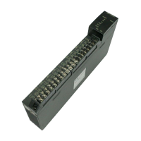
Details the names and descriptions of the components and indicators on the MASTER-K120S main unit.
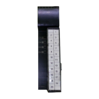
Provides specifications and diagrams for various expansion I/O modules, including digital and special modules.
Describes special modules such as A/D·D/A Combination, D/A Conversion, A/D Conversion, Analog Timer, and RTD Input.
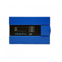
Details the specifications for various communication interface modules like Cnet, Fnet, Pnet, and DeviceNet.
Explains the optional modules available for the MASTER-K120S series, such as external memory and RTC modules.
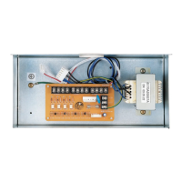
Details the power supply specifications for both standard and economic types of MASTER-K120S series.
Presents the CPU specifications for standard and economic types, including program control, memory, and operation modes.
Explains the PLC's operation processing methods, including cyclic and interrupt operations, and power failure handling.
Covers program classifications, execution procedures, interrupt programs, error handling, and operation modes.
Describes the four operating modes: RUN, STOP, PAUSE, and DEBUG, along with mode change methods.
Details essential PLC functions like self-diagnosis, I/O force control, direct I/O operation, and system error history.
Explains the memory structure of the CPU module, including program and data memory areas.
Describes the method for allocating I/O addresses to modules for reading input and writing output data.
Explains the structure and usage of the built-in Cnet selection switch for communication configuration.
Details the structure and usage of the external memory module for saving and loading programs safely.
Explains the structure and usage of the Real Time Clock (RTC) module for time-scheduling control.
Provides specifications for digital inputs and outputs, including maximum relay life for relay outputs.
Details digital input specifications for main units and expansion modules, including circuit diagrams and wiring.
Presents digital output specifications for main units (relay and TR output) and expansion modules.
Covers built-in functions like High-speed counter, Pulse Catch, Input Filter, External Interrupt, and PID control.
Details specifications and data registers for special modules: Combination, A/D, D/A, Analog Timer, and RTD Input.
Explains the positioning function, including specifications, operation patterns, instructions, and wiring for DRT/DT types.
Covers dedicated communication using built-in Cnet, including frame structure, commands, and data types.
Explains how to define and use custom communication protocols for MASTER-K120S via KGLWIN.
Details Modbus protocol support, including ASCII and RTU modes, basic specifications, and instructions.
Describes how to use No Protocol Communication for devices without standard protocols, covering sending and receiving data.
Explains remote connection methods using built-in Cnet, Modbus, Fnet, Profibus, and DeviceNet I/F modules.
Provides guidelines for installation environment, precautions, heat protection, and power consumption calculations.
Details wiring instructions for power supply, I/O devices, and grounding, including cable specifications.
Outlines daily and periodic maintenance checks for ambient environment, module play, and terminal conditions.
Lists daily inspection items focusing on terminal block connections and LED status for proper operation.
Covers periodic inspection items for ambient environment, PLC conditions, and connecting parts.
Provides basic instructions for troubleshooting, including visual checks, trouble checks, and narrowing down fault causes.
Explains procedures for determining causes of troubles, including flowcharts for LED status and I/O module issues.
A questionnaire to gather information when problems occur, to assist in contacting the service center.
Provides explanations of possible troubles with input and output circuits and their corrective actions.
Lists various error codes, their messages, CPU states, causes, and corrective actions for system troubleshooting.
Covers option settings including connect options, editor options for monitor display and auto save.
Details essential basic parameters for PLC operation, such as latch area, timer boundary, and watchdog timer.
Lists special relays (flags) used for editing user programs, providing function and description.
Explains the usage of D registers for storing communication function status and general data.
Details the D register mapping for Forced I/O setting, including designation and data registers.
Provides information on system error history and clock data storage when an RTC module is attached.
Shows the external dimensions (A and B) in mm for the main unit models.
Provides external dimensions for standard and slim type extension modules.
| Series | MASTER-K 120S |
|---|---|
| Input Voltage | 24 VDC |
| Program Memory | 8k Steps |
| Type | PLC |
| Output Type | Relay |
| Communication | RS-232 |
| Communication Ports | 1 |
| Programming Language | Ladder Diagram |
| Storage Temperature | -25 to 70°C |
| Humidity | 5 to 95% RH (non-condensing) |