Do you have a question about the LG MASTER-K Series and is the answer not in the manual?
Precautions for designing the PLC system for safety.
Precautions for safe installation of the module.
Precautions for testing and maintenance of the module.
Precautions for proper disposal of the module.
General environmental and physical specifications of the module.
Detailed performance characteristics of the high-speed counting module.
Electrical specifications for the module's input signals.
Specifications for limit switch inputs.
Electrical specifications for the module's transistor outputs.
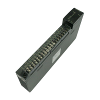
Identification and description of module hardware parts.
Explanation of the module's LED status indicators.
Configuration options using the module's DIP switches.
Details of the module's input and output terminal connections.
How the module interfaces with external hardware.
Description of different encoder output modes supported.
Detailed explanation of the module's various functions.
Explanation of the different operational modes for the counter.
Details on comparison signal generation and usage.
Functionality and operation of the home signal.
Explanation of the carry signal behavior.
Explanation of the borrow signal behavior.
Procedures and considerations for installing the module.
Environmental requirements for module installation.
Essential precautions for wiring the module.
Illustrative wiring examples for different encoder types.
Wiring example for 5VDC voltage output encoders.
Wiring example for 24VDC NPN open collector encoders.
Wiring example for 24VDC PNP open collector encoders.
Procedure for inserting function blocks into GMWIN.
Details and specifications of local function blocks.
Specifies the preset value for the High Speed Counter Module.
Specifies the comparison value for the High Speed Counter Module.
Writes run status control information for the High Speed Counter Module.
Reads current value and operating status of the High Speed Counter Module.
Details and specifications of remote function blocks.
Sets preset value for remote High Speed Counter Module.
Sets comparison value for remote High Speed Counter Module.
Writes operating status control info for remote module.
Reads operating status for remote High Speed Counter Module.
List and resolution of error codes for function blocks.
Programming examples for GM systems using the module.
Example demonstrating how to enable count operation.
Programming example for setting preset values.
Programming example for setting comparison values.
Programming example for setting magnitude comparison values.
Programming example for reading the current count value.
Programming example for enabling external output.
Programming example for coincidence reset function.
Programming example for carry/borrow reset function.
Programming example for enabling the home latch.
Programming for remote module read/write operations.
Practical application examples for the module.
Example program for controlling cart movement.
Block diagram illustrating the operational flow of the G3F-HSCA.
Configuration details for input/output signals of G3F-HSCA.
Input signal mapping for the G3F-HSCA module.
Output signal mapping for the G3F-HSCA module.
Input/Output signal mapping for G4F/G6F-HSCA modules.
Detailed functions of various input and output signals.
Configuration structure of the module's buffer memory.
Buffer memory layouts for G3F-HSCA and G4F/G6F-HSCA.
Details on the content and data format within buffer memory.
Methods for reading and writing to the buffer memory.
Instructions and methods for reading from buffer memory.
Instructions and methods for writing to buffer memory.
Programming examples for various functions.
Programming examples for setting preset values.
Setting preset values using external input on G6F-HSCA.
Programming examples for setting comparison values.
Programming examples for setting output data.
Programming examples for reading the current count value.
Programming examples for enabling outputs.
Programming examples for enabling the home latch.
Setting preset values using the home input signal.
Programming examples for coincidence reset.
Programming examples for carry/borrow reset.
Practical application examples for the module.
Example program for controlling cart movement.
Example program for controlling turntable constant angle rotation.
General troubleshooting overview for the module.
Troubleshooting based on module LED status.
Troubleshooting based on counting status issues.
Troubleshooting based on output status issues.
Step-by-step procedures for troubleshooting.
Procedure for troubleshooting incorrect LED indications.
Procedure for when counter operations fail.
Procedure for when count values are incorrect.
Procedure for when output operations do not execute.
List of errors indicated by LEDs and their corrections.
Physical dimensions and layout of the G3F-HSCA module.
Physical dimensions and layout of the G3F-HSCA module.
Physical dimensions and layout of the G4F-HSCA module.
Physical dimensions and layout of the G6F-HSCA module.
| Brand | LG |
|---|---|
| Model | MASTER-K Series |
| Category | Controller |
| Language | English |