5-12
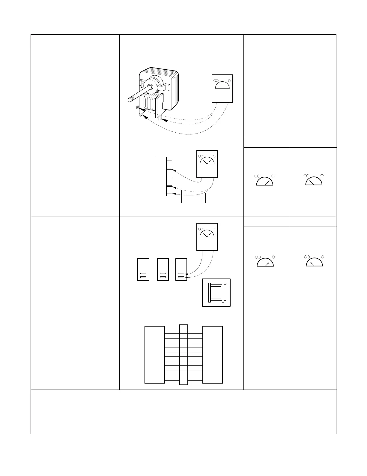
COMPONENTS TEST PROCEDURE RESULTS
CIRCULATION MOTOR
(Wire leads removed)
NOTE:
*( ) = WIRE COLOR
RELAY 3, 4, OF P.C.B
(Disconnect the 9 pin
connector from P.C.B)
See Schematic Dagram on
page 4-3)
RELAY 2, 3, 4 OF P.C.B
(Wire leads removed.)
RY5 : Microwave
RY4 : Grill
RY6 : Convection
KEY PCB
NOTE : A MICROWAVE ENERGY LEAKAGE TEST MUST ALWAYS BE PERFORMED WHEN THE UNIT IS
SERVICED FOR ANY REASON.
MAKE SURE THE WIRE LEADS ARE CORRECT POSITION.
WHEN REMOVING THE WIRE LEAD FROM THE PARTS, BE SURE TO GRASP THE
CONNECTOR, NOT THE WIRES.
Cooking Start OFF
Normal : COM-230V : Approx. 150 Ω
COM-24V : Approx. 20 Ω
Abnormal : Infinite or several ohm.
Check continuity between switch
terminals, by pressing an
appropriate pad on key board.
The contacts assignment of the
respective pads on the key board
is as shown left figures.
Measure the resistance.
(Multi-meter scale : R x 1)
 Loading...