Do you have a question about the LG MDD105 and is the answer not in the manual?
Notes on handling sensitive components like the pick-up unit during transport and repair.
Guidelines to prevent static discharge damage to electronic components.
Procedure for detecting and editing EEPROM options via remote control.
Steps for updating the unit's firmware via USB flash drive.
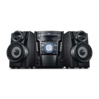
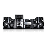
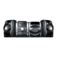
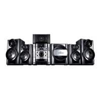
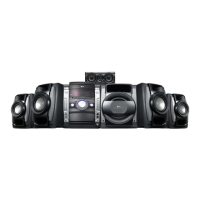
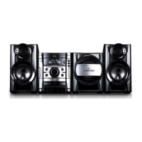
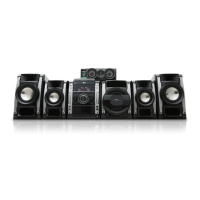
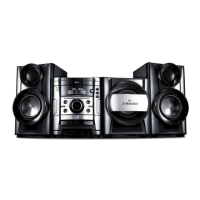
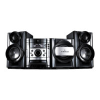
Detailed technical specifications for the DVD Mini Hi-Fi System's features and performance.
Visual breakdown of the main chassis components for identification.
Exploded view of the main unit's cabinet and internal frame assembly.
Exploded view of the tape transport mechanism.
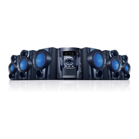
Exploded view of the speaker assembly.
Illustration of included accessories and packaging materials.
Troubleshooting guide for common electrical faults and symptoms.
Steps to diagnose and fix issues where the unit does not power on.
Guidance for troubleshooting when the Vacuum Fluorescent Display is not operational.
Troubleshooting steps for the disc tray mechanism failing to operate.
Specific troubleshooting for disc tray issues involving U4 and D8 components.
Troubleshooting disc tray faults related to IC401 and associated resistors.
Troubleshooting disc tray issues focusing on IC1 and communication resistors.
Steps to resolve problems where the unit fails to boot up after power-on.
Troubleshooting 'no booting' issues related to IC100 and its connections.
Troubleshooting 'no booting' issues related to the X100 crystal oscillator.
Troubleshooting 'no booting' issues related to the X101 crystal oscillator.
Steps to diagnose and fix issues with no speaker output or noise.
Troubleshooting speaker output problems related to IC700 and IC701.
Steps to troubleshoot when the VFD display remains blank after power-on.
Oscilloscope waveforms for IC1 MICOM interface during power on.
Oscilloscope waveforms for IC100 MICOM interface during normal play.
Oscilloscope waveforms for SLED drive and motor signals.
Oscilloscope waveforms for spindle drive and motor signals.
Oscilloscope waveforms for RF, Focus Error, and Tracking Error signals.
Schematic illustrating interconnections between PCBs and connectors.
Overall system block diagram showing component interactions.
Detailed circuit diagram of the Switched-Mode Power Supply.
Circuit diagram for the Main board's DVD MPEG processing section.
Circuit diagram for the Main board's Microcontroller Unit (MCU).
Circuit diagram for the Main board's Servo control system.
Circuit diagram for the Main board's Digital-to-Analog conversion circuits.
Circuit diagram for the Main board's Amplifier circuits.
Circuit diagram of the audio deck system.
Circuit diagrams for MIC, USB, Key, and VFD boards.
Chart listing test points and their corresponding expected voltages.
Top view of the Main Printed Circuit Board showing component placement.
Bottom view of the Main Printed Circuit Board showing solder side.
Diagram of the Switched-Mode Power Supply Printed Circuit Board.
Diagram of the Front Printed Circuit Board with controls and display components.
| Karaoke | Yes |
|---|---|
| Bass reflex | No |
| Speaker type | - |
| Audio decoders | Dolby Digital, Dolby Digital 5.1 |
| RMS rated power | 100 W |
| Number of speakers | 2 |
| Type | Home audio mini system |
| Product color | Black |
| Disc loading type | Tray |
| Number of optical discs | 1 discs |
| Recording on | CD, DVD, USB |
| Disc types supported | CD-R, CD-RW, DVD+R, DVD+RW, DVD-R, DVD-RW |
| Playback disc formats | CD audio, SVCD, VCD |
| Audio formats supported | MP3, WMA |
| Image formats supported | JPG |
| Video formats supported | DIVX |
| AM band range | 520 - 1720 kHz |
| FM band range | 87.5 - 108 MHz |
| Supported radio bands | FM, MW |
| Preset stations quantity | 50 |
| Apple docking compatibility | Not supported |
| Headphone connectivity | 3.5 mm |
| USB 2.0 ports quantity | 1 |
| Equalizer bands quantity | 5 |
| Battery type | AAA |
| Power source | AC |
| Cables included | RCA |