J
Juan PriceAug 14, 2025
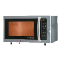
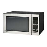
What to do if my LG MH-655T doesn't operate at all?
- QqmontoyaAug 14, 2025
If your LG Microwave Oven doesn't operate at all, and the display window shows nothing, it could be due to several reasons. The fuse might have blown and needs replacement. Alternatively, the magnetron thermostat or the power supply cord could be defective and require replacement. It may be necessary to replace primary and monitor switches.