Do you have a question about the LG MH-794GS and is the answer not in the manual?
Crucial safety measures for service personnel regarding microwave energy.
Warning about potential exposure to microwave radiation during operation.
Step-by-step guide for properly setting up the microwave oven.
Important guidelines for correctly earthing the microwave oven.
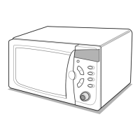
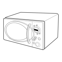
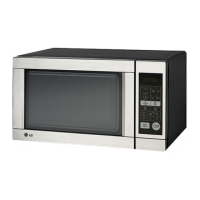
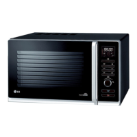
Overview of the microwave oven's key features and capabilities.
Detailed explanation of the microwave's control panel layout and functions.
Step-by-step guide on how to operate the microwave oven.
Details on Child Lock, Quick Start, More/Less, and Temperature settings.
Overview of electrical components, power control, and interlock systems.
Explanation of sequences for different cooking modes like microwave and grill.
List of essential tools and instruments for servicing the microwave.
Procedures and precautions for testing microwave energy leakage.
Techniques for measuring leakage with the case removed and assembled.
Guidelines for accurate measurement and documentation of results.
Instructions for removing outer case, power cord, and control panel.
Steps to remove door, transformer, capacitor, diode, and fan motor.
Guides for removing magnetron, turntable motor, heater motor, and sensor.
Procedures for removing PCB and installing/adjusting interlock systems.
Procedures to test continuity of primary, secondary, and monitor switches.
Methods to test resistance of high voltage transformer and magnetron.
Procedures to test key electrical components like capacitor, diode, fuse, and heater.
Methods to test continuity and resistance of relays, keypad, and sensor.
Diagnosing and resolving problems when the oven does not operate.
Troubleshooting issues with microwave cooking, grill, and uneven cooking.
Identifying and resolving error codes like E-01, E-02, E-03.
Detailed illustration of individual components within the door assembly.
Detailed illustration of individual components within the control panel assembly.
Detailed illustration of individual components within the oven cavity.
Detailed illustration of individual components within the latch board assembly.
Detailed illustration of individual components located inside the oven.
Detailed illustration of individual components of the base plate.
| Type | Microwave Oven |
|---|---|
| Capacity | 20 l |
| Power Output | 700 W |
| Control Type | Mechanical |
| Turntable | Yes |
| Weight | 10.5 kg |
| Microwave Power | 700 W |
| Color | Silver |
| Turntable Diameter | 245 mm |
| Voltage | 230 V |
| Frequency | 50 Hz |