6
3. Use the front panel fixing bolts to fasten the panel and the main body together.
- Refer to the user manual for the 4-Way front panel.
- After fixing the panel, remove the protective film from the exterior of the Human De-
tection Sensor kit.
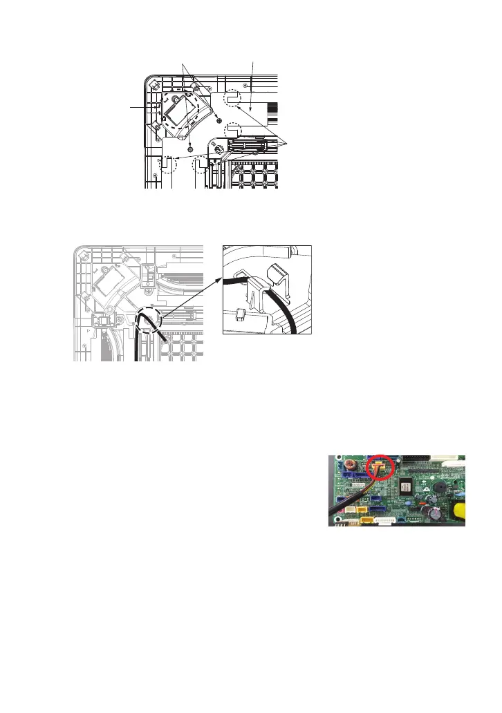
4. Detach the inlet grille from the panel and open the control
box cover of the main body
5. Refer to the wiring diagram attached to the control box
to connect all the connecting wires on the panel to the
connector inside PCB.
5-1. Connect the connecting wires of the kit to the yel-
low connector (CN_BLDC2) on the PCB as shown
in the figure.
6. Fasten the control box cover and attach the air Inlet grille.
7.
After completing the installation, check for normal operation by performing the following steps:
7-1. Set the installation direction of the sensor kit in the Installer Settings of the remote
control.
7-2.
After starting the operation, select 'Body Sensing Operation' in the 'Function Settings'.
7-3. Set ‘Body Sensing Wind Direction’ to ‘Direct Wind’ or ‘Indirect Wind’
7-4. Set to ‘Direct Wind’ and check if the vane that is in the direction of the motion de-
tected opens. Or set to ‘Indirect Wind’ and check if the vane that is in the direction
of the motion detected closes.
Figure. 5-1
Figure. 2-7
Fix with Hooks
2-7. Place the connecting wire inside the guide and fix it with the hooks, then attach the
motor cover.
2-6. Detach the motor cover by loosening two screws.
Figure. 2-6
Remove Screws
Display PCB
Motor Cover
Insulating Material
Attachment Parts