COMPONENT TESTING TIPS
7
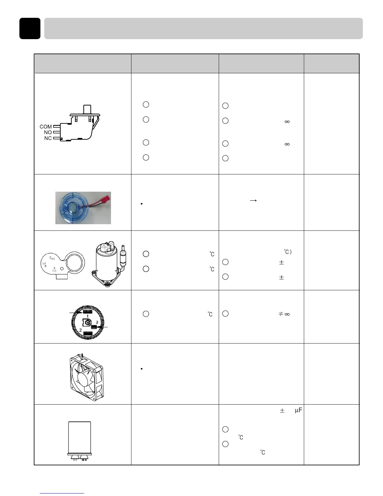
Component Test procedure Check result Remark
The state that
knob is Pressed is
opposite to open
condition
Measure resistance of the
Following terminal
1) Door switch knob : open
Measure resistance of the
Following terminal
Measure resistance of the
Following terminal
Measure capacitance of
Terminal to terminal
2)Door switch Knob : close
DC 12V
Power on Check the
voltage in
terminal.
Measure resistance of the
Following terminal
Red housing
-.2wire (BL & RED)
Red housing
-.2wire (BL & RED)
8.LED Lamp.asm
9.Compressor set
10.OLP
11. Cooling fan
12. Comp capacitor
7. Door S/W
Resistance value < 1Ω
Resistance value ÷
Resistance value ÷
Resistance value < 1Ω
Terminal : “COM”- “NC”
(1-3)
Terminal : “COM”- “NO”
(1-2)
Terminal : “COM”- “NC”
(1-3)
Terminal : “COM”- “NO”
(1-2)
1
2
1
2
Measure resistance of the
Following terminal
1
2
Measure resistance of the
Following terminal
DC 12V
Start-up Voltage: Up 6V
Rate current: 0.5A + 10%
Locked current: Under 1A
Resistance value(
25
Resistance: 8.64 7%Ω
RED & BLUE
Resistance: 2.59 7%Ω
BL & RED
1
2
1
Resistance value
1
2
1
2
1
2
Terminal : “C”- “R” at 25
Terminal : “C”- “S” at 25
Measure resistance of the
Following terminal
1
Terminal : “1”- “3” at 25
Capacitance value : 35 1.75
Check resistance
Stanby condition : 11.5
Ω
(25 )
Comp operation condition :
35~38
Ω
(25 )
1
2
16
 Loading...