Do you have a question about the LG RCAW and is the answer not in the manual?
Explains warning/caution symbols and their meanings for safe operation.
Covers essential safety guidelines for installation, operation, and maintenance to prevent hazards.
Guides users on manipulating the Human Machine Interface (HMI) unit for operation.
Details navigation through menus like Main Menu, User Setting, I/O Display, Alarm, System, and Parameter.
Configures control sequence and alarm determination delays for chiller operation.
Introduces the PLC and HMI components, keys, and display for chiller control.
Outlines the control menu structure and the indication status of LEDs for system monitoring.
Explains PLC DIP switches, MODBUS configuration, and register map for communication.
Details connector locations, pinouts, and RTD/MODBUS connections for wiring.
Describes Hand Mode and Auto Mode for turning the machine on and off.
Lists critical checks to perform before attempting to start the chiller.
Provides a step-by-step guide for initiating the chiller's operation.
Specifies the acceptable operating temperature and voltage limits for the unit.
Details flow rate requirements and chilled water pressure drop characteristics.
Explains the step-by-step sequence of chiller operation, including delays and fan control.
Covers the RTD sensors used for monitoring temperatures and their resistance data.
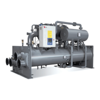
Illustrates cooling cycle components and describes the compressor's construction and operation.
Lists common compressor issues, causes, remedies, and protection methods.
Provides guidance on condenser coil cleaning and condenser fan assembly.
Describes flow, pressure, and anti-freezing switches for unit control and safety.
Details procedures for refrigerant/oil charging, and components like filters and valves.
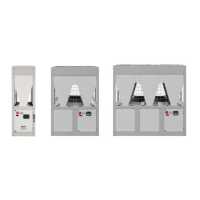
Shows the physical layout of the power and control panels.
Covers power panel components: starters, OCRs, voltage monitoring, and relays.
Explains contactors, and internal control panel components like PLC, sensors, and fans.
Introduces general troubleshooting steps for unit malfunctions and system issues.
Lists various alarms, their recognition, possible causes, and recommended remedies.
Provides detailed electrical wiring diagrams for unit components.
Illustrates the refrigerant and oil cycle with a component legend.
Offers checklists for project information, model details, equipment checks, and start-up parameters.