Do you have a question about the LG S33A1-D and is the answer not in the manual?
Precautions for handling electrostatically sensitive devices to prevent damage.
Details on accessing and using hidden modes via the remote control for service.
Information on firmware update procedures and required filenames.
Procedures for factory reset and setting option codes via EEPROM.
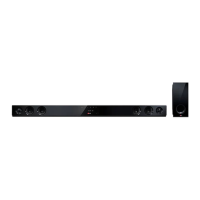
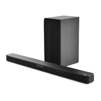
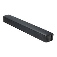
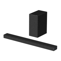
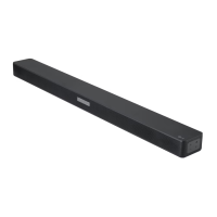
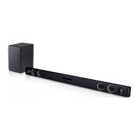
Technical specifications of the soundbar system, including power and dimensions.
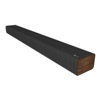
Exploded view of the receiver bar components for assembly and repair.
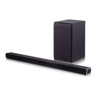
Exploded view of the wireless subwoofer components for assembly and repair.
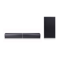
List and illustration of included accessories with the product.
Troubleshooting guide for common receiver bar issues with solutions.
Flowcharts for diagnosing power supply and system operational issues.
Oscilloscope waveform examples for key system signals and test points.
Diagrams illustrating electrical connections between PCBs and modules.
Overall and power block diagrams showing system architecture.
Detailed circuit schematics for SMPS and main electronic boards.
Table of IC voltage specifications and measured values during operation.
Visual layout of components on SMPS, MAIN, and FRONT PCBs.
| Brand | LG |
|---|---|
| Model | S33A1-D |
| Category | Speaker System |
| Language | English |