EasyManua.ls Logo

LG XAS14F User Manual

LG XAS14F
47 pages
To Next Page IconTo Next Page
Page #1 background imageLoading...
Page #1 background image
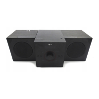
MICRO Hi-Fi SYSTEM
SERVICE MANUAL
MODEL:
XA14 (XAS14F)
CAUTION
BEFORE SERVICING THE UNIT, READ THE “SAFETY PRECAUTIONS”
IN THIS MANUAL.
MODEL:
XA14
(XAS14F)
SERVICE MANUAL
0102,MAY39726747NFA:ON/P
Website http://biz.lgservice.com
Internal Use Only

Other manuals for LG XAS14F

Questions and Answers:

LG XAS14F Specifications

General IconGeneral
BrandLG
ModelXAS14F
CategoryStereo System
LanguageEnglish

Summary

Section 1: Summary

Product Safety Servicing Guidelines

Guidelines for safe servicing of audio-video products, including hazards and installation tips.

Servicing Precautions

Essential safety measures for servicing, including handling ES devices and insulation checks.

Service Information for EEPROM

Procedure for updating EEPROM data, including steps for detecting and writing new EEPROM.

Program Update Guide

Instructions for updating system firmware via USB for ESS, SANYO, and MCS programs.

Specifications

Technical specifications for the LG Micro Hi-Fi System XA14, covering general, tuner, amplifier, CD, and speakers.

Section 2: Cabinet & Main Chassis

Exploded Views

Visual representation of the unit's internal components and their assembly for the main chassis.

Cabinet and Main Frame Section

Detailed breakdown of the unit's cabinet and main frame components with part identification.

Packing Accessory Section

Illustration and list of accessories included in the product packaging, such as remote and battery.

Speaker Section (XAS14F)

Diagrams illustrating the left (A60L) and right (A60R) speaker units for the XAS14F model.

Section 3: Electrical

Electrical Troubleshooting Guide

Step-by-step guide to diagnose and resolve issues with the SMPS (Switch Mode Power Supply) part.

Waveforms

Oscilloscope waveforms for CD searching, spindle drive, and motor operations, detailing signal patterns.

Wiring Diagram

Diagram illustrating the electrical connections and wiring between different printed circuit boards (PCBs).

Block Diagrams

Main system block diagram detailing the interconnection of major functional units like MCU, DSP, and AMP.

Circuit Diagrams

Detailed schematic of the SMPS (Switch Mode Power Supply) circuit, including component layout and connections.

Circuit Voltage Chart

Table listing test points and their expected DC voltage values for diagnostic purposes.

Printed Circuit Board Diagrams

Top and bottom views of the main printed circuit board (PCB) showing component placement.

Related product manuals