Do you have a question about the LGMG AR45J and is the answer not in the manual?
Defines key terms for manual clarity.
Outlines personnel qualifications and machine status requirements.
Lists preparatory steps before starting maintenance.
Specifies environmental and site conditions for safe operation.
Details crucial safety measures for maintenance and repair.
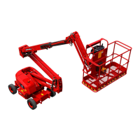
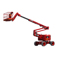
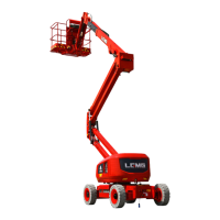
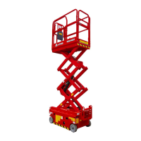
Clarifies the specific purpose for which the machine is designed.
Provides general information on maintenance processes.
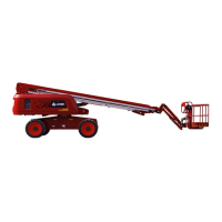
Lists key technical specifications and performance data for machine models.
Detailed specifications for the AR45J model.
Detailed specifications for another AR45J variant.
Detailed specifications for the AR52J model.
Detailed specifications for another AR52J variant.
Provides guidelines for setting correct torque values for fasteners.
Lists key components and their associated torque values and intervals.
Details the steps for assembling the platform components.
Details the steps for assembling the jib components.
Details the steps for assembling the cable carrier.
Details the steps for assembling the boom and extension jib.
Details the steps for assembling various cylinders.
Details the steps for assembling the folding jib.
Details the assembly procedures for the Kubota engine.
Details the assembly procedures for the Deutz engine.
Details the assembly procedures for the tank side components.
Details the assembly of the rotary table swing mechanism.
Details the assembly of the front and rear axles.
Details the procedure for bleeding various cylinders in the hydraulic system.
Covers assembly of miscellaneous components.
Details various valve assemblies and their components.
Outlines operator and technician responsibilities for maintenance.
Guidance on inspecting and maintaining labels and signs on the machine.
Procedure for daily checks of machine components for damage or missing parts.
Steps for checking the hydraulic oil level and specifications.
Procedure for checking hydraulic oil for leaks.
Guidance on inspecting battery condition and maintenance.
Procedure for inspecting wiring harnesses and connectors.
Inspection procedure for tires and hubs for safe operation.
Steps for checking and maintaining oil levels in drive hubs.
Importance of checking the hydraulic oil tank exhaust cover for proper function.
Guidelines for visually inspecting hydraulic oil quality.
Procedure for lubricating the platform weighing structure.
Steps for replacing the hydraulic tank return filter.
Steps for replacing the high-pressure filter element.
Procedure for replacing drive hub gear oil.
Steps for replacing the air cleaner element.
Maintenance and lubrication procedures for the slewing drive.
Procedure for changing hydraulic oil and replacing the suction filter.
Maintenance procedures specific to Deutz engines.
Maintenance procedures specific to Kubota engines.
Overview of scheduled maintenance intervals.
A table listing engine faults, causes, and measures for troubleshooting.
Lists DTC codes, SPN, FMI, inspection items, and set parameters for engine faults.
Provides a schedule for routine and periodic maintenance tasks.
Crucial safety precautions to follow before and during commissioning.
Outlines essential tests to perform during the commissioning phase.
Procedures for testing system and functional overflow pressures.
Lists machine fault codes (DTC) and their descriptions.
Provides electrical schematic diagrams for the machine.
Provides hydraulic schematic diagrams for the machine.
Illustrates common symbols used in hydraulic diagrams.
Illustrates common symbols used in electrical diagrams.
| Brand | LGMG |
|---|---|
| Model | AR45J |
| Category | Boom Lifts |
| Language | English |