Do you have a question about the Lian-Li Q58 and is the answer not in the manual?
Details the function and location of the power switch.
Describes the front panel I/O ports including USB and audio jacks.
Specifies the bracket for SFX and SFX-L power supply units.
Mentions the inclusion or use of a power extension cord.
Lists supported fan sizes and radiator configurations.
Highlights the toolless installation for 2.5" SSD trays.
Describes the integrated LED and fan control hub.
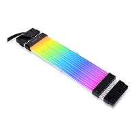
Refers to the PCIe extension cable for GPU mounting.
Details the bracket at the bottom for fans or SSDs.
Details the function and location of the power switch.
Describes the front panel I/O ports including USB and audio jacks.
Lists ATX PSU size limits and supported fan/radiator sizes.
Mentions the inclusion or use of a power extension cord.
Highlights the toolless installation for 2.5" SSD trays.
Describes the integrated LED and fan control hub.
Refers to the PCIe extension cable for GPU mounting.
Details the bracket at the bottom for fans or SSDs.
Lists screws for mounting motherboards and 2.5" SSDs.
Describes anti-vibration rings for SSD and HDD mounts.
Specifies screws used for PSU installation.
Lists screws specifically for 2.5" SSD mounting.
Details the spacers used for 3.5" HDD installation.
Specifies screws for mounting fans.
Lists M3-sized screws for 2.5" SSDs.
Lists 6#32-sized screws for 3.5" HDDs.
Provides cable ties for wire management.
Provides Velcro straps for cable management.
Includes spare plastic clips for various uses.
Describes the expansion rack for 3.5" HDD or 2.5" SSD.
Details the bracket designed for ATX power supply units.
Includes a magnetic dust filter for air intake.
Lists 6#32 screws for securing the expansion rack.
Description of the power button's location and function.
Details the combined audio and microphone jack.
Describes the USB 3.1 Type-C port.
Details the USB 3.0 port and its connection.
Describes the USB 3.1 Gen 2 port and its connection.
Details the HD Audio connector pinout.
Explains the power connectors and LED definitions.
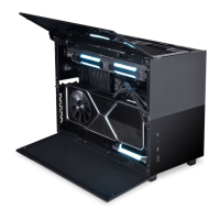
Showcases the standard appearance of the computer case.
Illustrates the case with a mesh top and glass bottom.
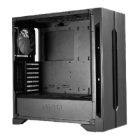
Displays the computer case from the motherboard side.
Displays the computer case from the GPU side.
Instructions for removing the top panel of the case.
Guides for detaching the side and front panels.
Steps to detach the bottom fan bracket.
Information regarding the symmetrical nature of side panels.
Instructions to remove screws from the front PSU bracket.
Instructions to remove screws from the motherboard PSU bracket.
Steps for detaching the main power supply bracket.
Guide for mounting the PSU onto its dedicated bracket.
Connects the power cord to the installed PSU.
Secures the GPU cable before proceeding with installation.
Guidance on installing an extra 2.5" SSD.
Re-attaching the PSU bracket with the SFX PSU installed.
Instructions for routing the GPU cable behind the PSU bracket.
Reminder to connect the PCIE cable to the motherboard.
Steps to remove the screws securing the top fan bracket.
How to adjust fan/water cooling for preferred air inlet.
Instructions for using water-cooling specific screws.
Verifying the correct front orientation for installation.
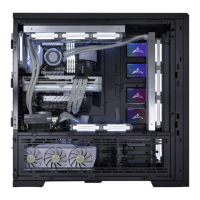
Mounting the water cooling unit onto the fan bracket.
Ensuring correct tube placement and fan mounting.
Opening the LED fan hub to prevent installation conflicts.
Guide for inserting the radiator into the chassis.
Placement notes for the water tube and fan.
Removing the SSD tray to gain space for water cooling.
Steps for adjusting and securing the top fan bracket.
Attaching the expansion rack to the top fan bracket.
Reminder to connect HDD cables before cooling installation.
Details compatibility between storage drives and fans.
Guide for installing AIO radiators alongside HDDs.
Describes the motherboard's 5V-ARGB connection port.
Details the hub's 5V-ARGB output connection.
Details the hub's fan output connections.
Instructions for connecting the hub to the motherboard fan header.
Procedure to open the hub for connecting cables.
Information on the optional screw fixation for SSDs.
Details mounting options for 2.5" SSD or 120mm fan.
Instructions for installing the magnetic dust filter.
Instructions to remove screws from the front PSU bracket.
Instructions to remove screws from the motherboard PSU bracket.
Steps for detaching the top fan bracket.
Steps for detaching the main power supply bracket.
Guides for installing various cooling components.
Details fan and radiator support limitations.
Procedure for routing the tube before installing the bracket.
Important warning about correct bracket placement.
Reminder to connect the PCIE cable to the motherboard.
Instructions for installing the magnetic dust filter.
Information on the optional screw fixation for SSDs.
Details support for expandable 2.5" SSD/HDD configurations.
Indicates the correct direction for cable routing.
Steps for sliding and securing a component.
Instructions for tightening a thumbscrew.
Re-attaching the fan bracket after managing cables.
Clearance specifications for SFX/SFX-L PSUs in standard position.
Clearance details related to SFX/SFX-L PSU screw hole locations.
Specifies the clearance requirements for ATX PSUs.
Details the available clearance space for graphic cards.
Shows the maximum clearance height for CPU coolers.
Specifies the clearance for 240mm All-In-One liquid coolers.
Initial steps: install components and enter motherboard BIOS.
Configure PCIe slot signal from Auto/Gen4 to Gen3 in BIOS.
Save BIOS settings and then remove the GPU.
Connect the PCIe 3.0 riser cable to motherboard and GPU.
Restart the system and proceed with OS installation.
Chinese language instructions for PCIe 4.0 system setup.
German guide: install components and enter motherboard BIOS.
German guide: configure PCIe slot signal to Gen3 in BIOS.
German guide: save BIOS settings and remove the GPU.
German guide: connect the PCIe 3.0 riser cable.
German guide: restart the system and install the OS.
Spanish guide: install components and enter motherboard BIOS.
Spanish guide: configure PCIe signal from Auto/Gen4 to Gen3.
Spanish guide: save BIOS settings and power off the PC.
Spanish guide: connect the PCIe 3.0 riser cable.
Spanish guide: restart the system and install the OS.
Japanese guide: install components and enter motherboard BIOS.
Japanese guide: set PCIe slot signal from Auto/Gen4 to Gen3.
Japanese guide: save BIOS settings and power off the PC.
Japanese guide: remove the GPU.
Japanese guide: connect the PCIe 3.0 riser cable.
Japanese guide: restart the system and install the OS.
| Case Type | Mini-ITX |
|---|---|
| Material | Aluminum, Steel, Tempered Glass |
| Motherboard Support | Mini-ITX |
| Expansion Slots | 3 |
| Power Supply Support | SFX/SFX-L |
| Maximum GPU Length | 320 mm |
| Maximum CPU Cooler Height | 67 mm |
| Color | Black, White |
| Weight | 4.5 kg |
| Drive Bays | 2 x 2.5" or 1 x 3.5" |
| Front I/O Ports | 1 x USB 3.1 Type-C |
| Radiator Support | 120mm |
| Cooling Support | 1 x 120mm fan (top) |