EasyManua.ls Logo

Liberty Pumps OilTector OTC Series User Manual

Liberty Pumps OilTector OTC Series
24 pages
To Next Page IconTo Next Page
Page #1 background imageLoading...
Page #1 background image
7000 Apple Tree Avenue, Bergen, NY 14416 | Phone: (800) 543-2550 | Fax: (585) 494-1839 | www.LibertyPumps.com
1
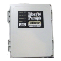
Operation, Maintenance, and Installation Manual | 7613000A
OilTector
®
Control Panel System
Single Phase Simplex | Type 4X (Indoor/Outdoor)
Models: OTC Series, Opaque Door, Local and Remote Alarm
Read all instructions thoroughly. Installation of the OilTector® control system must comply with all federal, state, and local
codes, regulations, and practices. The control system must be installed by qualified personnel familiar with all applicable
local electrical and mechanical codes. Refer to the National Electrical Code (NEC) (NFPA 70). Failure to properly install and
test this product can result in personal injury or equipment malfunction.
The OilTector control system is designed and approved for the safe operation of pumping, alarming, and monitoring of
elevator sump pits, transformer vaults, and leachate well applications. The OilTector control panel will activate a pump to
remove water from pits in accordance with ASME A17.1, stopping the pump before oil or other harmful substances enter the
water supply. The control panel includes LED indicators that will illuminate while monitoring various conditions including
but not limited to: power, pump running, high oil, high water, power loss, level sensor error detection (if enabled), fire alarm
mode (if enabled), and low level alarm/redundant o (if enabled). The included alarm buzzer and/or auxiliary contacts will
activate on power loss, high oil, high water, or the various alarm conditions. The system also includes auxiliary contacts for
pump run monitoring. The alarm auxiliary contacts of the control panel are connected to the OilTector remote alarm panel
which provides audio and visual indication of an alarm condition with built-in auxiliary contacts for connection to a building
automation system (BAS) or SCADA system and phone dialers.
The OilTector control panel menu system with rotary encoder interface and OLED display screen provides indication of
the current system status and access to configurable features including: level sensor error detection, automatic or manual
alarm condition reset, function input to be used for a fire system or low level/redundant o float switch, and a weekly pump
exerciser. An integrated pump hand-o-auto (HOA) selector switch is included to set the desired operation mode of the
pump. Refer to additional information in this manual for: multiple auxiliary contact outputs, navigating menu system, change
system settings or configurations, system setup with the setup wizard, system displayed statistics, and user input presets.
Introduction
Safety Guidelines
1. DISCONNECT ALL ELECTRICAL SERVICE BEFORE WORKING ON OR HANDLING THE OILTECTOR SYSTEM.
2. DO NOT USE WITH FLAMMABLE OR EXPLOSIVE FLUIDS SUCH AS GASOLINE, FUEL OIL, KEROSENE, ETC.
DO NOT USE IN EXPLOSIVE ATMOSPHERES. SENSOR MODULE SHOULD ONLY BE USED WITH WATER.
3. DO NOT HANDLE THE OILTECTOR CONTROL SYSTEM WITH WET HANDS, WHEN STANDING ON A WET OR
DAMP SURFACE, OR IN WATER.
4. INCOMING VOLTAGE MUST MATCH OILTECTOR CONTROL SYSTEM VOLTAGE.
5. TO PREVENT ELECTRICAL SHOCK AND EQUIPMENT MALFUNCTION, USE ONLY WITH A PUMP SUPPLIED
WITH A GROUNDING CONDUCTOR AND GROUNDING-TYPE ATTACHMENT PLUG. MAKE SURE TO PLUG THE
OILTECTOR CONTROL PANEL INTO A PROPERLY GROUNDED, GROUNDING-TYPE RECEPTACLE.
6. CONTROL PANEL CAN BE MOUNTED INDOOR OR OUTDOOR. ALARM PANEL MUST BE MOUNTED INDOOR.
FOR OUTDOOR ALARM APPLICATIONS, CONSULT FACTORY.
7. SECURE THE PRESET LEVEL SENSOR MODULE ON THE DISCHARGE PIPE AT A LEVEL THAT GUARANTEES
PARTIAL PUMP SUBMERGENCE WHEN THE WATER LEVEL IS JUST BELOW THE PUMP STOP PROBE
(longest probe; see step 2 on page 5 of this manual). FAILURE TO PROPERLY MOUNT THE PRESET LEVEL
SENSOR MODULE MAY CAUSE UNINTENDED CONSEQUENCES.
8. CAUTION! REMOVE ANY FLOAT SWITCH THAT IS CURRENTLY USED OR SUPPLIED WITH THE PUMP. IF THE
FLOAT CANNOT BE REMOVED, SECURE FLOAT SWITCH SO THAT IT IS ALWAYS ON.
IMPORTANT
Refer to the included electrical schematic for all incoming power connections and pump connections which may include
optional field wiring connections. This manual covers models: OTC-115-230W and OTC-115-230W-5. System includes: control
panel with local alarm (beacon, buzzer, and test/silence switch), remote alarm panel, and preset level sensor module.

Questions and Answers:

Liberty Pumps OilTector OTC Series Specifications

General IconGeneral
BrandLiberty Pumps
ModelOilTector OTC Series
CategoryControl Systems
LanguageEnglish

Summary

Introduction to OilTector Control System

System Purpose and Compliance

Explains the OilTector control system's purpose, compliance, and installation requirements.

Safety Guidelines

Electrical and Operational Safety Precautions

Details critical safety rules for handling the system, including electrical disconnect and fluid compatibility.

Control Panel Overview and Specifications

Standard Features and Components

Lists key components of the control panel, including enclosure, indicators, and switches.

Electrical and Sensor Specifications

Details specifications for power, inputs, outputs, sensors, and enclosure.

Description of Operation

System Functionality and Alarms

Explains how the system operates, including pumping, alarming, and LED indicators.

Menu System Interface

Display Screen and Navigation Controls

Describes the OLED display, RGB LEDs, and rotary scroll wheel for system interaction.

Menu System Navigation and Settings

Menu Scroll Wheel Functions

Explains basic functions of the scroll wheel for navigation, selection, and value changes.

Display Screen Navigation Conventions

Describes arrow indicators on the display screen for menu navigation and action prompts.

Changing System Settings Procedure

Guides on how to access and modify system settings via the menu path and password.

Control Panel Installation

Mounting Location and Securing

Instructions for determining mounting location and securing the control panel using screws.

Preset Level Sensor Installation

Sensor Mounting and Cable Routing

Guidance on attaching the sensor to the discharge pipe and routing its cable.

Preset Level Sensor Operation

Pumping Range Explanation

Explains the fixed and adjustable pumping ranges based on sensor probes.

Float Switch and Oil Probe Installation

Sensor Arrangement and Mounting

Details the installation of float switches and oil probe for different application configurations.

System Wiring Configurations

Preset Level Sensor Wiring

Details wiring connections for the 5-conductor preset level sensor to the control panel.

Multi-Float and Oil Probe Wiring

Details wiring for 3-4 control float switches and an oil probe to the control panel.

Function Input (FI) Wiring

Fire Alarm and Low Level Input Connections

Explains wiring for fire alarm or low level/redundant off float switch inputs to FLT 2.

Remote Alarm Panel Wiring

Connecting Control Panel to Alarm Panel

Details how to connect control panel auxiliary contacts to the alarm panel's input terminals.

Auxiliary Contacts Functionality

Trouble Alarms and Pump Run Monitoring

Explains the function of auxiliary contacts for pump trouble alarms and pump run monitoring.

Pump Connections

Motor Contactor Wiring

Details how to connect the pump power cable to the motor contactor terminals (M1).

Incoming System Power Wiring

Connecting Line and Neutral Wires

Instructions for wiring incoming system power using WAGO connectors to TB-L1 and TB-N.

Incoming Pump Power Wiring

Connecting Pump Circuit Breaker

Details wiring the pump power cable to the pump circuit breaker's L1 and L2/N terminals.

Application Examples and Sensor Types

3-Probe and Float System Applications

Describes applications using a 3-probe sensor with fixed or adjustable pumping range.

3-4 Floats and Probe System Applications

Describes applications using control switches and an oil probe for customized pumping range.

Setup Wizard for Quick Configuration

3-Probe and Float System Setup

Guides through setting up the system for 3-probe applications and entering pump FLA.

3-4 Floats and Probe System Setup

Guides through setting up the system for 3-4 float and probe applications and entering pump FLA.

Clearing Alarms and User Input

Alarm Clearing Procedure

Steps to clear displayed alarm conditions from the main screen by interacting with the menu.

Pump Hand-Off-Auto (HOA) Switch Operation

Operating Modes (Hand, Off, Auto)

Explains the three operating modes of the HOA switch and their corresponding LED indicators.

Alarm Test, Silence, and Buzzer Functions

Performing an Alarm Test

Describes how to perform an alarm test, its sequence, and expected results.

Silencing the Alarm Buzzer

Explains how to silence the alarm buzzer during an alarm condition using the test/silence switch.

OilTector Remote Alarm Panel Introduction

Safety Guidelines for Alarm Panel

Critical safety precautions for handling and installing the remote alarm panel.

Remote Alarm Panel Specifications

Details power, contacts, LEDs, buzzer, enclosure, and certifications for the alarm panel.

Remote Alarm Panel Operation Description

Explains how the alarm panel indicates high oil, high water, and other alarm conditions.

Alarm Panel Installation Procedures

Battery Installation and Testing

Steps for installing and testing the 9VDC battery backup for the alarm panel's power feature.

Mounting Location and Power Connection

Guidance on selecting a mounting location and connecting the alarm panel's power outlet.

Alarm Panel Wiring Connections

Connecting to Alarm Security Systems (BAS)

How to connect alarm panel outputs to BAS or other external monitoring devices.

Connecting Control Panel Auxiliary Contacts

How to wire control panel auxiliary contacts to the alarm panel's input terminals.

Finalizing Alarm Panel Installation and Testing

Wire Routing and Power Supply Connection

Instructions for routing wires and plugging in the alarm panel power supply into a wall outlet.

Alarm Panel Testing Procedure

How to test the alarm panel's LEDs, buzzer, and auxiliary contacts for proper function.

OilTector Control Panel System Testing

HOA Switch and Pump Operation Test

Verifies HOA switch operation and pump start/run behavior in AUTO mode.

High Oil and High Water Alarm Tests

Tests the high oil and high water alarm functions by simulating alarm conditions.

Power Loss Event Simulation Test

Tests the remote alarm panel's response to a power loss condition by simulating it.

Optional System Configurations

Setting the Pump Exercise Timer

Configures the timer for periodic pump activation to maintain pump health when idle.

Changing the System Password

Procedure to modify the system password to prevent unintended changes to settings.

Understanding the Config Code

Explains the config code for system snapshot decoding by customer support.

System Settings and Configurations

General System Settings Configuration

Configures auto error reset, silence time, LED brightness, and password.

Pump Set Up Configurations

Sets up high amp alarm, pump enable, current sensor, and exercise intervals for pump 1.

Input Set Up Options Configuration

Configures input presets, probe sensitivity, and error input behavior for sensors.

Menu System Statistics and Navigation

Quick Stats and Main Menu Access

Navigates the menu for system normal inputs, sensor status, and main menu options.

Resettable and Lifetime Statistics Viewing

Accesses and interprets resettable and lifetime system event data like pump stats and liquid stats.

System Configuration Summary

System Type and Setup Wizard Settings

Configures system type, pump FLA, and error reset settings within the setup wizard.

Pump and Input Configuration Settings

Sets up pump parameters like high amp alarm and input sensor configurations.

Basic Troubleshooting Guide

Pump Operation Issues

Addresses problems like pump not running, stopping early, or running continuously.

Alarm and Sensor Error Troubleshooting

Solves trouble alarms, high oil alarms, sensor errors, and float switch obstructions.

Related product manuals