EasyManua.ls Logo

Life Fitness G4-001 User Manual

Life Fitness G4-001
31 pages
To Next Page IconTo Next Page
Page #1 background imageLoading...
Page #1 background image
G4 GYM SYSTEM
ASSEMBLY INSTRUCTIONS
G4-001 / CLASS H / 09/19/08 / 8604101 / REV B-2

Other manuals for Life Fitness G4-001

Question and Answer IconNeed help?

Do you have a question about the Life Fitness G4-001 and is the answer not in the manual?
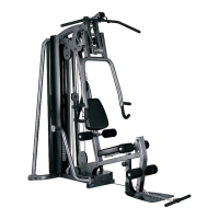
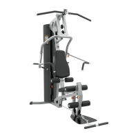
Life Fitness G4-001 Specifications

General IconGeneral
BrandLife Fitness
ModelG4-001
CategoryHome Gym
LanguageEnglish

Summary

Important Safety Information

Access Control

Recommends supervised area for fitness equipment use.

Installation

Recommends securing equipment to a solid, level surface.

Proper Usage

Guidelines for safe and proper operation to avoid injury.

Inspection

Operating Warnings

Selectorized Weight Stack Systems

Important Notes

Tools Required for Assembly

Bolt Length Ruler

Gym Layout

Minimum Required Usable Space

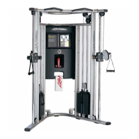
Specifies the minimum dimensions for safe operation.

Dimensions Including GLP Leg Press (optional)

Lists dimensions for the gym system with optional leg press.

Parts List

Components Parts List

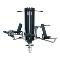
List of major components with keys and descriptions.

Hardware Parts List

List of hardware parts with keys and descriptions.

Figure 1: Assembly Steps

Step 1: Assemble Base Plates to Frame and Base

Loosely assemble base plates to frame and base using bolts and nuts.

Step 1: Assemble Footplate to Frame

Loosely assemble footplate to frame using bolt and nut.

Figure 2 & 3: Assembly Check

Check Weight Plates and Head Plate Assembly

Verify correct assembly of weight plates and head plate as shown.

Figure 4: Weight Stack Assembly

Step 4: Assemble Weight Stack Components

Assemble weight stack components including guide rods, spacers, plates, and head plate.

Step 4: Apply Weight Stack Labels

Apply weight stack labels to plates and head plate correctly.

Figure 5: Rear Uprights and Boom Plates

Step 5: Assemble Rear Uprights to Base

Securely assemble right and left rear uprights to the base.

Step 5: Assemble Boom Plates to Rear Uprights

Securely assemble boom plates to the rear uprights.

Figure 6: Boom Plates to Frame

Step 6: Assemble Boom Plates to Frame

Securely assemble left and right boom plates to the frame.

Step 6: Slide and Tighten Shaft Collars

Slide and securely tighten shaft collars on the guide rods.

Figure 7: Pec Fly Arms Assembly

Step 7: Tighten Frame Connections

Tighten frame connections, excluding the footplate/frame connection.

Step 7: Slide Pec Fly Arms over Base

Slide the left and right pec fly arms over the base.

Step 7: Assemble Pec Fly Handles to Pec Fly Arms

Assemble pec fly handles to the pec fly arms using bolts and washers.

Figure 8: Pec Plate and Arms to Base

Step 8: Assemble Pec Plate and Pec Fly Arms

Assemble pec plate to base and pec fly arms to base.

Figure 9: Leg Pedestal Assembly

Step 9: Assemble Leg Pedestal, Roller Pads, and Caps

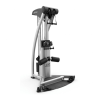
Assemble leg pedestal, roller pads, and roller pad caps.

Figure 10: Seat Assembly

Step 10: Assemble Seat Pad, Roller Pads, and Seat Adjust Assembly

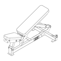
Assemble seat pad, roller pads, and seat adjust assembly into frame.

Figure 11: Back Pad Assembly

Step 11: Assemble Back Pad, Back Incline Adjust, and Roller Pads

Assemble back pad, back incline adjust, and roller pads.

Figure 12: Press Arm Support Components

Step 12: Assemble Press Arm Support Components

Assemble press arm support pivot, bearing blocks, and adjustment plate.

Figure 13: Press Arm Pivot Shaft

Step 13: Assemble Press Arm Pivot Shaft and Spring Pin Connection

Assemble press arm pivot shaft and connect press arm using spring pin.

Figure 14: Lat Cable Routing

Step 14: Route Lat Cable and Assemble Pulley

Route LAT cable through frame and assemble pulley.

Figure 15: Lat Cable Routing

Step 15: Route Lat Cable Around Pulley and Assemble Pulley to Boom Plates

Route LAT cable around pulley and assemble pulley to boom plates.

Figure 16: Lat Cable Routing

Step 16: Route Lat Cable Through Press Arm Support Frame

Route LAT cable through frame and assemble pulley.

Step 16: Route Lat Cable Through Frame

Route LAT cable through frame and assemble pulley.

Step 16: Route Lat Cable Around Pulley to Bracket Assembly

Route LAT cable around pulley and assemble pulley to bracket assembly.

Figure 17: Lat Cable Routing

Step 17: Route Lat Cable Around 4-1/2” Pulley to Boom Plates

Route LAT cable around pulley and assemble to boom plates.

Step 17: Assemble Plastic Sleeves to Boom Plates

Securely assemble plastic sleeves to boom plates.

Step 17: Route Lat Cable Around 3-1/2” Pulley to Plates

Route LAT cable around pulley and assemble to plates.

Step 17: Route Lat Cable Over 3-1/2” Pulleys to Boom Plates

Route LAT cable over pulleys and assemble to boom plates.

Step 17: Screw Lat Cable End to Head Plate Assembly

Screw the threaded end of LAT cable to head plate assembly.

Figure 18: Pec Fly Cable Assembly

Step 18: Assemble Pec Fly Cable to Left and Right Pec Arms

Securely assemble PEC FLY CABLE to left and right pec arms.

Step 18: Assemble Pulleys to Pec Plates and Base Plates

Assemble pulleys to pec plates and base plates using various hardware.

Step 18: Route Pec Fly Cable Around 4-1/2" Pulley to Bracket Assembly

Route PEC FLY CABLE around pulley and assemble to bracket assembly.

Figure 19: Guide Cable Routing

Step 19: Screw Guide Cable into Bracket and Secure Guide Cable

Screw GUIDE CABLE into bracket and secure guide cable.

Step 19: Route Guide Cable Around Pulley to Plates

Route GUIDE CABLE around pulley and assemble pulley to plates.

Step 19: Route Guide Cable to Base

Route hook end of GUIDE CABLE to BASE.

Figure 20: Low Cable Routing

Step 20: Route Low Cable Around V-Pulley to Frame

Route LOW CABLE around V-PULLEY and assemble pulley to FRAME.

Step 20: Route Low Cable Through Base Plates and Assemble Pulleys

Route LOW CABLE through base plates and assemble pulleys.

Figure 21: Low Cable Routing

Step 21: Route Low Cable Around Pulley to Pulley Bracket

Route LOW CABLE around pulley and assemble pulley to pulley bracket.

Step 21: Route Low Cable Through Base Plates and Assemble Pulley

Route LOW CABLE through base plates and assemble pulley.

Figure 22: Low Cable Routing

Step 22: Assemble Pulley to Foot Plate

Assemble pulley to FOOT PLATE using bolt, spacers, and nut.

Step 22: Route Low Cable Around Pulley to Leg Pedestal

Route LOW CABLE around pulley and assemble pulley to LEG PEDESTAL.

Figure 23: Final Adjustments and Attachments

Step 23: Check Head Plate Seating and Adjust Cable System

Check head plate seating, push down, insert pin, perform repetitions, adjust cable.

Step 23: Attach Lat Bar to Lat Cable

Attach the LAT BAR to the ball end of LAT CABLE using a SNAP LINK.

Step 23: Attach Ankle Strap to Link Chain

Attach the ANKLE STRAP to the 12 LINK CHAIN using a SNAP LINK.

Step 23: Attach Ab Strap to Low Cable

Attach the AB STRAP to the ball end of LOW CABLE using a SNAP LINK.

Parts List and Figure 24 Assembly

Parts List for Shrouds and Brackets

List of parts for shrouds and brackets.

Parts List for Hardware

List of hardware for shrouds and brackets.

Step 24: Assemble Top Shroud Bracket to Boom Plates

Securely assemble top shroud bracket to right and left boom plates.

Parts List and Figure 25 Assembly

Parts List for Shrouds and Brackets

List of parts for shrouds and brackets.

Parts List for Hardware

List of hardware for shrouds and brackets.

Step 25: Assemble Shrouds to Brackets

Securely assemble left and right shrouds to top and bottom shroud brackets.

Step 25: M4 Hardware for Exercise Cards

M4 hardware pre-assembled for hanging G4 Exercise Cards.

Maintenance

Cleaning, Inspection, and Lubrication Recommendations

Recommendations for cleaning, inspecting, and lubricating the equipment.

Record Model, Serial, Date, Dealer Information

Record equipment details for service and warranty.

Warranty

Limited Warranties (Frame, Parts, Cables, Upholstery)

Details of lifetime and three-year limited warranties for various components.

Warranty Conditions, Exceptions, and Claims

Conditions that void warranty, claim procedures, and owner rights.

Warranty Limitations and Disclaimers

Limitations on implied warranties and disclaimers of liability.

Corporate Headquarters and International Offices

North America, Latin America, Brazil Contact Information

Contact details for Life Fitness in North America, Latin America, and Brazil.

Europe, Middle East, Africa (EMEA) Contact Information

Contact details for Life Fitness across EMEA regions.

Asia Pacific (AP) Contact Information

Contact details for Life Fitness in Japan, China, Hong Kong, and other AP regions.

Related product manuals