1.1.1 Control unit wiring diagram of the lower part
Terminals Description
BLACK CABLE COMMON ELECTRONIC AND AUXILIARY POWER SUPPLY
GEAR MOTOR RELEASE SWITCH
0
BLACK CABLE
-
RED CABLE
DARK BLUE
GREEN
STOP PLATE and ENCODER
TRANSFORMER POWER SUPPLY
+
BLACK
A
B
C
D
E
16
CLOCKWISE ROTATION
COMMON
BROWN CABLE
BLUE CABLE
ANTI-CLOCKWISE ROTATION
CAPACITOR
230Vac MOTOR OUTPUT
WHITE CABLE
24
B1
ORANGE CABLE
COMMON
FC1
FC2
ATTENTION: the connections pre-wired by the manufacturer may not be altered under any circumstances.
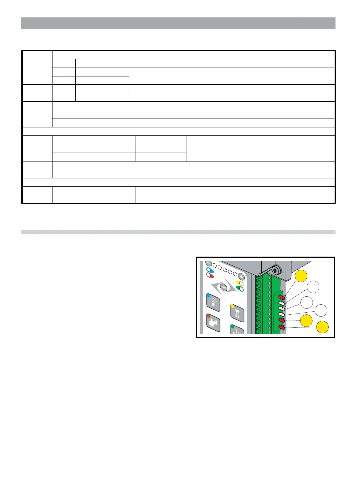
1.1.2 Indicator LEDs
There is a row of 6 LEDs on the right hand side of the board, under the terminals.
These LEDs are lit when the corresponding signal is present.
For N.C. inputs STOP, PHOTO1 and PHOTO, the corresponding LEDs L7, L11
and L12 are normally on.
For the N.O. inputs OPEN, CLOSE and STEP, the corresponding LEDs L8, L9
and L10 will be switched off. These LEDs therefore indicate any malfunction of
the connected devices.
L7
L8
L9
L10
L11
L12
 Loading...