• Use the power supply cable provided with the operator only.
• The power cable provided may not be extended or shortened
• All wires must be unsheathed as little as possible (6mm at the most), as close as
possible
to the connection terminals, in order to prevent accidental contact with live parts should the
cables disconnect from the terminals.
• Do not pre-seal cables to be fastened to the terminals using screws.
• If it is possible that wires subject to voltage higher than 50 Volt RMS and very low voltage
s
afety wires may come into contact with one another, wires with voltage higher than 50 volt RMS must be insulated with a sheath; or the very low
voltage safety wire must have an insulating sheath at least 1mm thick.
• No external connection cables must be of the flat twin tinsel cord type.
1.2.1 Setting up the electric system and connection to the mains supply
This manual does not describe how the electrics system should be prepared for connection to the mains. It does, however, give the following warnings:
• The electricity supply line must be installed and connected by an authorised electrician or professional fitter.
• The electricity supply must be adequately protected against short circuits and static discharge.
• T
he power supply network must contain an omnipolar circuit breaker with a contact opening distance equal to or greater than 3.5 mm that
assures the complete disconnection of the power supply.
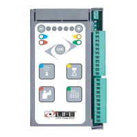
1.2.3 Control unit connections
Fitters must make the connections of the 230 Vac 50 Hz electricity supply, and the various automation devices.
Connections between the control unit, motor, encoder and transformer have already been performed by the Manufacturer.
• O
nce the connections to the control unit have been made, the Fitter must use bands to join adjacent wires into groups of 2, 3 or 4 in order to prevent
t
hem coming away from the terminal board: bands must be attached as close as possible to the terminals, no more than 10mm away, taking care not
to damage wire insulation. No cable may remain unpaired.
• The bands are only for unsheathed cables (sheathed cables are held in place by the sheath).
• Pay careful attention not to pair wires with voltages higher than 50 Volt RMD with lower voltage wires.
• The wiring performed internally by the manufacturer is already equipped with clamping bands.
Internal button panel.
Sensitive strip (signal)
3x1 mm
2
cable
2x1 mm
2
cable
ATTENTION: the cables used must be suited to the type of installation.
It is the Fitter
’s responsibility to choose appropriate material.
Pos. Type of cable
Connection
Electricity supply line
Internal button panel.
Sensitive strip (signal)
Power supply
Flashing light
Radio aerial
Tx Photo
Rx Photo
Selector
3x1,5 mm
2
cable
Cable supplied with Schuko socket
Screened RG58 50 Ω cable
4x1 mm
2
cable
2x1 mm
2
cable
2x1 mm
2
cable
3x1 mm
2
cable
3x1 mm
2
cable
2x1 mm
2
cable
1.2 List of electric cables
The cables needed may vary depending on the installation and type and quantity of devices installed.
The cables used in the installation must be IEC 60335 compliant.
FUSES
Two internal Fuses
a)F1 protects the secondary 24v supply against
transformer overload
Technical: Mini fuses 5x20 T10 A certi cated by IEC
60127 or EN 60127
b)F2 protects the primary 24v supply against motor
overload
Technical: Mini fuses 5x20 T1 A certi cated by IEC
60127 or EN 60127

 Loading...