B100 Quick Start Manual 2
© 2015 LifeSafety Power Inc.P03-005 01/15
LifeSafety Power Inc.
304 Terrace Drive
Mundelein, IL 60060 USA
www.lifesafetypower.com
Tel (888) 577-2898
info@lifesafetypower.com
Important: All information, including illustrations, is believed to be reliable. Users, however, should independently evalu-
ate the suitability of each product for their particular application. LifeSafety Power makes no warranties as to the accuracy or
completeness of the information, and disclaims any liability regarding its use. LifeSafety Power’s only obligations are
those in the LifeSafety Power Standard Terms and Conditions of Sale for this product, and in no case will LifeSafety Pow-
er or its distributors be liable for any incidental, indirect, or consequential damages arising from the sale, resale, use, or mis-
use of the product. Specifications are subject to change without notice. In addition, LifeSafety Power reserves the right to make
changes—without notification to Buyer—to processing or materials that do not affect compliance with any applicable specification.
1
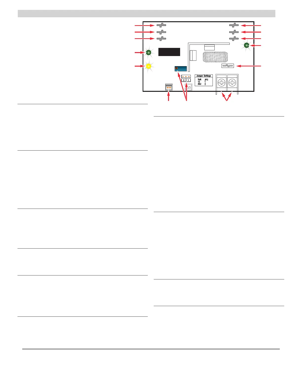
DC IN Connectors (J1 & J4)
These fastons are the input to the B100. Either faston may be
used as the input. Two connections are provided to allow this
voltage to pass through to other accessory boards in the sys-
tem. This input voltage must always be at least 3 volts above
the output voltage setting for the B100 to maintain its output.
2
DC OUT Connectors (J2 & J5)
These fastons are the output of the B100 for connection to other
accessories in the system. This output may be considered as an
equivalent to the DC1 faston of an FPO power supply. Either or
both DC OUT fastons may be used in the system.
I Ensure there are no other voltage sources
connected to the buss before powering the system
or damage WILL occur.
3
BR Connectors (J3 & J6)
The DC Common buss in the system. All boards in the
system must have their BR fastons wired together for
proper operation (except for between the DC and AC sec-
tions of an FPX hybrid system).
4
DC IN LED (D1) – Green
This LED indicates the availability of voltage on the DC IN
Buss. When voltage is available on the buss, the LED is lit.
5
FAULT LED (D7) – Yellow
This LED lights when the B100 detects a fault condition. This
fault condition also transmits to the FPO power supply
.
Fault conditions detected include ruptured output fuse, no
output, output overload, or output voltage out of regulation.
6
FlexIO Connectors (JP1 & JP2)
These connectors allow the fault status of the B100 to be
transmitted to the FPO power supply and pass the FlexIO
buss on to other accessory boards in the system.
7
Output Voltage Selection (JP3 & VR1)
This jumper selects the output voltage for the B100 and
the potentiometer sets the output voltage when in the ad-
justable range. In adjustable range, voltage may be set
from 5 to 18VDC. Possible jumper settings are as follows:
• 12V Out JP3 Position 1
• Adjustable OutputJP3 Position 2
I The VR1 potentiometer will have no effect unless the
jumper is set for the adjustable range.
Note that the input must be at least 3V above the output voltage
setting or the B100 will display a fault condition. It may be help-
ful to temporarily set the input power supply to 24V (Remove
load devices first) before setting the B100 output voltage.
8
DC Output
This is the output terminal strip. This terminal strip is
non-removable and accepts wire sizes from AWG12 –
AWG22. The terminals are labeled on the PC board by the
terminal strip.
I
CAUTION When powering magnetic loads such as
maglocks, door strikes, solenoids, etc, each of these loads
must have a reverse protection diode either built-in or external
to the device.
9
Output Fuse (F1)
This fuse protects the DC Output terminals. It does not pro-
tect the DC OUT faston.
bk
DC OUT LED (D4) – Green
This LED indicates the availability of voltage on the DC OUT
Buss. When voltage is available on the buss, the LED is lit.
B100
DC IN
DC OUT
BR
DC IN
BR
DC OUT
– OUT +
Fault
DC In
DC Out
 Loading...