FlexPower Vantage R8 Access Power System - Installation Manua 3
FPV4 Power Supply Overview -
I
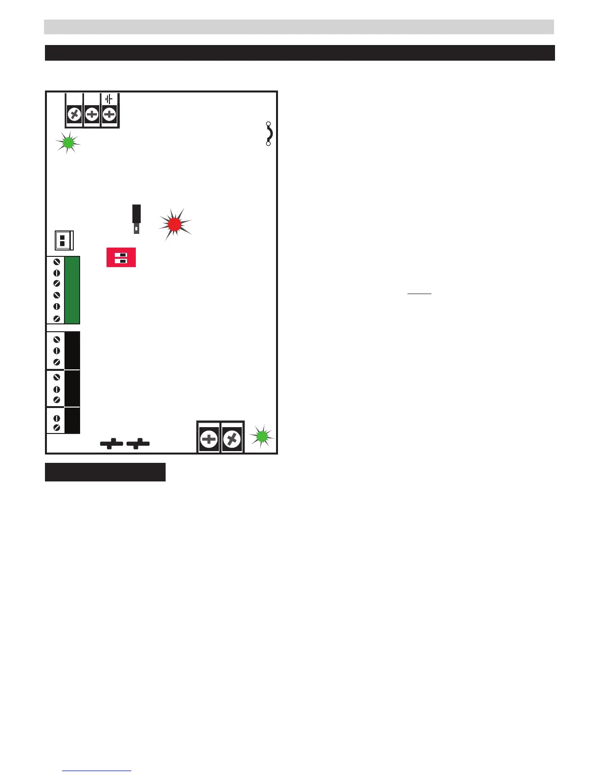
Read before Power Up
This guide gives the basic information needed to install a system containing a single Vantage Power Supply for most applications.
I For FPV6, FPV102, FPV104 - see page 4
+
–
FAI and Charge
Current settings
FAI
N
L
Observe
battery polarity
or damage may result
Observe
battery polarity
or damage may result
i
AC Select
Voltage Select
FlexIO
12V
24V
cut jumper for
230VAC
DC ON
AC ON
ON
1 2
SYS FLTSYS FLT
AC FLTAC FLT AUXAUX
FAI INPUTFAI INPUT
FPV4
I
ALWAYS DISCONNECT POWER BEFORE CHANGING
OUTPUT VOLTAGE TO PREVENT PS DAMAGE
1
AC Voltage Select Jumper - -
Leave INTACT for 120V input. CUT for 230V input.
I Failure to cut this jumper when using the FPV with a 230VAC
input will result in damage to the system and void the warranty.
2
AC Input primary AC connection.
3
AC LED (GREEN) indicates a valid AC input voltage is pres-
ent. Missing AC is indicated by this LED extinguishing.
H Always confirm the absence of AC power with a meter
before servicing to prevent electric shock.
4
Voltage Selection Jumper selects the output voltage
between 12V and 24V DC.
I Remove AC input power before changing the voltage select switch
to avoid damaging the power supply or connected equipment.
5
FAI LED (RED) indicates activation of the Fire Alarm Input.
IFor FAI wiring see page 9.
6
Flex IO Connector Supplies FAI status to any accessory
boards. Receives fault signal from accessory boards.
7
FAI and Charge Current Configuration Switches
Switch 1 - FAI Selection
Off = Constant Output
On = Output switches on FAI
Switch 2 - Charge Current
Off = High Charge Current
On = Low Charge Current
8
FAI Input The input from the FACP. Can be wired to accept
a NO, NC, Open Collector, or Voltage input.
See page 6 for FAI wiring information.
9
System Fault Contact - Contact labeling is adjacent to the
terminals and shown in the unpowered (FAULT) condition.
bk
AC Fault Contact Contact labeling is adjacent to the
terminals and shown in the unpowered (FAULT) condition.
AC fault is indicated on a missing AC Input voltage.
bl
Auxiliary Voltage is a fixed Class 2 DC output.
bm
Battery Terminal Connection for the optional
battery backup. Battery set voltage must match
the DC output voltage setting.
bn
Main DC Output of the power supply. The output
can either be constant or switched based on the
configuration setting of switch.
• The DC ON LED will be green with voltage present.
 Loading...