FlexPower Vantage R8 Access Power System - Installation Manual 4
FPV6, 102, 104 Power Supply Overview -
I
Read before Power Up
This guide gives the basic information needed to install a system containing a single Vantage Power Supply for most applications.
1
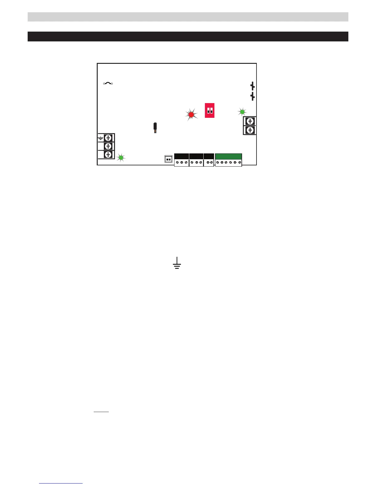
AC Input Voltage Selection
Leave INTACT for 120V input. CUT for 230V input (models
ending in "/E" have jumper precut for 230VAC input).
I Failure to cut this jumper when using FPV power sup-
ply with a 230VAC input will result in damage to the system
and void the warranty.
2
AC Input Terminal Block
The primary AC connection. Connect Hot Line to terminal
"L", neutral to terminal "N" and earth ground to terminal
For 230VAC input cut JP1 Jumper (see #1 above).
I Models ending in "/E" are factory pre-set for 230VAC input.
3
AC ON LED (green)
Indicates a valid AC input voltage is present. Missing AC is
indicated by this LED extinguishing.
H Always confirm the absence of AC power with a meter
before servicing to prevent electric shock.
4
FAI LED (red)
Indicates activation of the Fire Alarm Input.
5
12/24V Selection Jumper (model FPV6 only)
This selects the output voltage between 12V and 24V DC
on FPV6 models. The FPV power supply must be com-
pletely powered down before changing this setting. Volt-
age markings are printed on the PC Board adjacent to the
selector.
I Remove AC input power before changing the voltage select
jumper to avoid damaging the power supply or connected equipment.
I Models FPV102 and FPV104 are a fixed output voltage:
FPV102: 12V / 10 Amps
FPV104: 24V / 10 Amps
6
Charge Current / Main output FAI Configuration Switches
Switch 1 - FAI Selection I Switch must remain Off.
FAI selection made on R8 board - page 9.
Switch 2 - Charge Current
Off = High Charge Current | On = Low Charge Current
7
FLEX IO Connector
Supplies FAI status to any accessory boards. Receives fault
signal from accessory boards.
8
System Fault Contact
The System Fault contact output. Contact labeling is ad-
jacent to the terminals. When at fault, the NO-C contact is
open, NC-C contact is closed (relay not energized).
9
AC Fault Contact
The AC Fault contact output. Contact labeling is adjacent to
the terminals. When AC is lost, the NO-C contact is open,
NC-C contact is closed (relay not energized).
bk
AUX Output
The auxiliary voltage is fixed Class 2 Power Limited DC output.
bl
FAI Input
The input from the FACP. Can be wired to accept a NO, NC,
Open Collector, or Voltage input.
See page 6 for FAI wiring information.
bm
Main Output
This is the main DC output of the power supply.
bn
Battery Terminal Connection
The connection for the optional backup battery. Battery set
voltage must match the DC output voltage setting.
12/24VDC jumper
on FPV6 only
preset to 12V
FAI INPUTFAI INPUT
SYS FLTSYS FLT
AC FLTAC FLT AUXAUX
N
L
FPV6 12/24V @ 6A
FPV102 12V @ 10A
FPV104 24V @ 10A
+
–
AC INPUT
FlexIO
Observe battery polarity
or damage may result
Observe battery polarity
or damage may result
AC Select
cut jumper for
230VAC
For UL compliance, the AC fault contact
must be monitored by a listed control panel
1
2
ON
1 2
AC ON
DC ON
FAI and Charge
Current settings
+
–
ON
1 2
For UL compliance, the AC fault contact
must be monitored by a listed control panel
N
L
FPV4
AC INPUT
AC Select
cut jumper for
230VAC
FlexIO
AC ON
DC ON
FAI and Charge
Current settings
12V 24V
SYS FLTSYS FLT
AC FLTAC FLT AUXAUX
FAI INPUTFAI INPUT
FAI
 Loading...