FlexPower Vantage R8 Access Power System - Installation Manua 5
R8 Power Control Accessory Module Overview
1
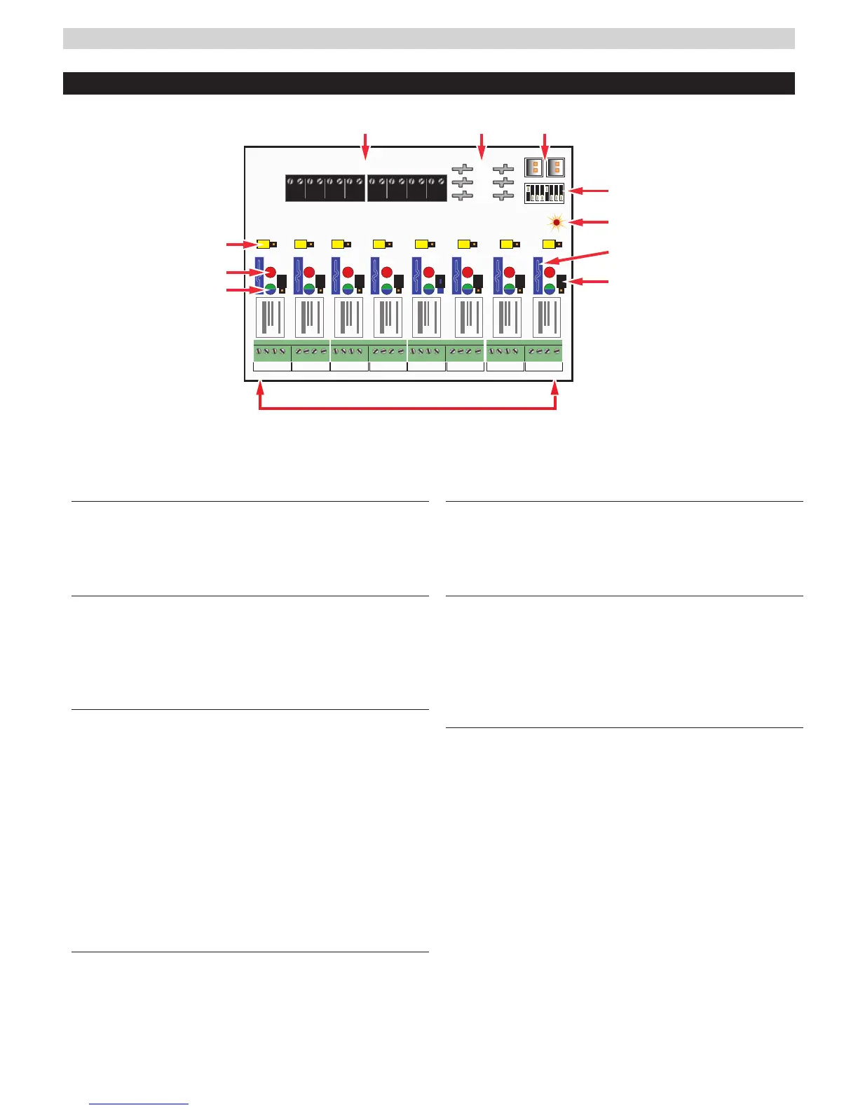
FlexIO Connectors
These connectors pass the FAI signal to the R8/R8P
board and pass the FlexIO buss on to other accessory
boards in the system.
2
B1, B2, and BR Connectors
These connectors are the voltage inputs for the R8/R8P board.
BR is the DC Common buss in the system. B1 is the positive
voltage input for the first power supply. In dual voltage sys-
tems, B2 is the input for the second power supply.
3
Zone Inputs (IN1 – IN8)
These are the zone input terminal strips. These terminal
strips are removable and accept wire sizes from AWG14
– AWG22. The terminals are labeled on the PC board
near the terminal strip. See the Input Wiring section of
this manual for more information.
• When using a normally open relay contact input, the
contact is connected across the IN and GND terminals.
• When using an open collector (transistor) input, the
open collector it connected to the IN terminal. Note
that the input source must be common grounded
with the
R8/R8P
board’s power source.
4
Voltage Selection Jumpers (Yellow)
These jumpers select the power input to be used for
each output. For single voltage systems, this jumper
should stay in the B1 position. this jumper should be
removed on any zones where a dry contact output is
needed.
5
Relay State LEDs (Red)
These LEDs indicate the state of the output relay.
The LED will be lit when the relay is active and extin-
guished when the relay is not active.
6
Output Voltage LEDs (Dual Color - Blue/Green)
These LEDs indicate the voltage of the zone’s output.
• BlueThe output is set to 24V
• GreenThe output is set to 12V
• OffFuse or PTC open or dry contact output se-
lected
7
Zone Outputs (01 – 08)
These are the zone output terminal strips. These ter-
minal strips are removable and accept wire sizes from
AWG14 – AWG22. The terminals are labeled on the PC
board near the terminal strip. See the Output Wiring
section for more information.
• C, NC, and NO are the relay output.
– The C terminal will always have voltage present
when the yellow jumper is installed, regardless of
relay state.
– NC will have voltage when the relay is NOT AC-
TIVE. Use for Fail Safe locks.
– NO will have voltage when the relay is ACTIVE.
Use for Fail Secure locks.
• COM is the DC common terminal for the output
I CAUTION When powering magnetic loads such as
maglocks, door strikes, solenoids, etc, each of these
loads must have a reverse protection diode either built-
I The relay contact outputs have suppression diodes across them. For a dry contact output, the output
diodes must be cut and the yellow and black jumpers removed.
GND GND GND GND
1 2 3 4
GND GND GND GND
5 6 7 8
INPUT 1 - 4 INPUT 5 - 8
FAI
1
8
GND GND GND GND
1 2 3 4
GND GND GND GND
5 6 7 8
NC C N0 COM NC C N0 COM
OUTPUT 1 OUTPUT 2
NC C N0 COM NC C N0 COM
OUTPUT 3 OUTPUT 4
NC C N0 COM NC C N0 COM
OUTPUT 5 OUTPUT 6
NC C N0 COM NC C N0 COM
OUTPUT 7 OUTPUT 8
B2
BR
B1 B2 B1 B2 B1 B2 B1 B2 B1 B2 B1 B2 B1 B2 B1 B2
B1
 Loading...