1
TOOLS REQUIRED TABLE OF CONTENTS
ASSEMBLY INSTRUCTIONS
MODEL 9594
SAVE THIS INSTRUCTION IN THE EVENT THAT THE MANUFACTURER HAS TO BE CONTACTED FOR REPLACEMENT PARTS.
CONTACT LIFETIME CUSTOMER SERVICE:
Dial 1-800-225-3865
7:00 am–5:00 pm (M–F) MST
and 9:00 am–1:00 pm (Sat) MST
QUESTIONS?
Model Number: 9594
Product ID:
For Customer Service in Mainland Europe and
the United Kingdom,
E-mail: cs@lifetimeproducts.eu
Live Chat:
www.lifetime.com/customerservice
(Click on the "LIVE CHAT" tab)
BACKBOARD & RIM COMBO
MOUNTING KIT
BEFORE ASSEMBLY:
• There are three ways to install this mounting kit: to a
pole, a roof or a wall. Follow the instructions carefully
to successfully complete the assembly. You should
only use two of the instructional sections:
1. Combo assembly, sections 1, 2 or 3, depending on your combo, i.e.,
Impact™, Fusion™ or metal-framed backboard
2. 9594 kit assembly and installation, sections 4, 5 or 6, depending on
your installation type, i.e., to a pole, a roof or a wall
You will also use the
Parts Identifi er
pages
The
Parts Identifi er
,
located at the center of this manual,
consists of four yellow pages displaying all the
parts and hardware included with both the 9594
kit and the purchased backboard & rim combo. It
can be removed from these instructions and used
as a quick reference throughout the assembly and
installation. Use the
Parts Identifi er
to
verify that all
parts and hardware are included and in working
order.
• At least 3 adults are recommended for setup.
Icon Legend..................................................................2
Warnings & Notices......................................................3
What to Expect............................................................4
Impact™ Backboard & Rim Assembly.........................5
Fusion™ Backboard & Rim Assembly.........................12
Steel-Framed Backboard & Rim Assembly..................20
Parts Identifi er.................................i–iv
Pole-Mount Assembly................................................33
Roof-Mount Assembly................................................38
Wall-Mount Assembly................................................43
Registration.......................................................50
Warranty..........................................................51
TOOLS REQUIRED
(x2) (x1) (x2)
(x2)
(x1) (x1)
(x1)
(x1)
(x1)
1/2" (≈13 mm)
3/8" (≈10 mm) 1/2" (≈13 mm)
9/16" (≈14 mm)7/16" (≈11 mm)
3/4" (≈19 mm)
(x3)
(x1)
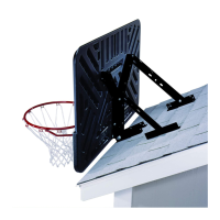
There are three installation options. The installer is responsible for selecting mounting hardware
suitable for a roof or wall mount option.
Pole Mount
Wall Mount
Roof Mount
(x3)