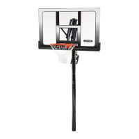
Do you have a question about the Lifetime CRANK ADJUST 90568 and is the answer not in the manual?
Crucial safety guidelines and warnings for assembly and operation to prevent injury or damage.
Precautions for safely handling and moving the glass backboard to prevent breakage.
Instructions for digging the foundation hole for the basketball pole base, including dimensions and depth.
Attaching nuts to J-bolts, inserting them into the template, and securing the center bolt with a coupler.
Mixing and pouring concrete into the hole, and placing rebar for structural support.
Centering the template over the hole, inserting J-bolts, and ensuring the template is level and sloped.
Sliding the flared end of the top pole onto the swaged end of the bottom pole, ensuring alignment.
Striking the pole ends against a surface to ensure proper seating of the pole sections.
Using a screw to secure the top pole to the bottom pole.
Attaching the pole brackets to the top pole section using specified hardware.
Securing the lower extension arm assembly to the pole using washers and hardware.
Installing hardware in the specified location for connecting the upper extension arms.
Attaching the upper extension arms to the pole using the specified hardware and washers.
Aligning the crank adjust assembly spacer with the lower extension arms and securing with hardware.
Installing hardware to connect the crank adjust assembly and handle brackets, using plastic spacers.
Placing the rim impact spacer and housings onto the backboard, finger-tightening hardware.
Securing the rim adapter plate to the backboard with hardware, finger-tightening for now.
Sliding the rim pin into the rim and attaching it to the rim housing with washers.
Sliding the spring holder clevis onto the eye bolt and securing it with hardware, finger-tightening.
Installing the compression spring onto the eye bolt and tightening nuts to adjust rim tension.
Securing all previously installed hardware from steps 5.1-5.5 in the order they were assembled.
Attaching the Rim Cover Plate to the Rim using the specified hardware.
Attaching the lower extension arms to the backboard using hardware, with assistance required.
Attaching the upper extension arm to the backboard using the specified hardware.
Repeating step 6.2 to attach the second upper extension arm to the backboard.
Stacking star washers onto the exposed ends of the J-bolts.
Attaching the basketball net to the rim.
Aligning pole slots with J-bolts, lifting the pole with assistance, and securing it to the template.
Securing the pole into position by sliding washers onto J-bolts and tightening nuts.
Using a level to adjust nuts, ensuring the pole plate is level and the backboard hangs plumb.
Tightening the hex nuts on the pole plate to secure the assembly and ensure verticality.
Placing plastic caps onto the exposed ends of each J-bolt.
Adjusting backboard height and applying the height sticker to the crank mechanism.
Guidance on checking hardware, wear, corrosion, and applying paint for rust prevention.
Details of the 5-year limited factory warranty, including exclusions and limitations.
| Brand | Lifetime |
|---|---|
| Model | CRANK ADJUST 90568 |
| Category | Sports & Outdoors |
| Language | English |


 Loading...