EasyManua.ls Logo

Lifetime V-STEEL STRONG ARM 90585 User Manual

Lifetime V-STEEL STRONG ARM 90585
44 pages
To Next Page IconTo Next Page
Page #1 background imageLoading...
Page #1 background image
TOOLS REQUIRED TABLE OF CONTENTS
Pour le français, voir la page 2. Para el español, ver la página 3.
ASSEMBLY INSTRUCTIONS
MODEL 90585
CONTACT LIFETIME CUSTOMER SERVICE:
QUESTIONS?
MODEL# AND PRODUCT ID
(you will need both when contacting us)
Model Number: 90585
Product ID:
V-STEEL STRONG ARM
BASKETBALL SYSTEM
Icon Legend..................................................4
Warnings & Notices.....................................5
Pole Assembly...............................................6
Pole-to-Base Assembly..............................10
Backboard-to-Rim Assembly.....................13
Backboard-to-Pole Assembly.....................18
Parts Identifi er..........................................i–iv
Handle Assembly........................................23
Final Assembly............................................26
Maintenance Instructions..........................33
Warning Sticker...........................................35
Registration..............................................36
Warranty....................................................37
(2)
(1)
(1)
(1)
(1)
(1)
(1)
1/2" (≈13 mm), 9/16" (≈14 mm),
3/4" (≈19 mm), 5/8" (≈16 mm)
310 lb (≈141 kg)
1/2" (≈13 mm)
(1)
(1)
3/16" (≈5 mm)
(included)
(2)
Save this instruction in the event that the manufacturer has to be contacted for replacement parts.
BEFORE ASSEMBLY:
Decide with what to fi ll the base
(sand is recommended)
At least 2 people recommended for setup
3D ANIMATION
OF THE FULL ASSEMBLY
WATCH
SCAN THE
CODE
OR SEARCH
1197940
Dial 1-800-225-3865
7:00 am–5:00 pm (M–F) MST
and 9:00 am–1:00 pm (Sat) MST
For Customer Service in Mainland
Europe and the United Kingdom,
E-mail: cs@lifetimeproducts.eu
Live Chat:
www.lifetime.com/customerservice
(Click on the "LIVE CHAT" tab)
Question and Answer IconNeed help?

Do you have a question about the Lifetime V-STEEL STRONG ARM 90585 and is the answer not in the manual?

Lifetime V-STEEL STRONG ARM 90585 Specifications

General IconGeneral
BrandLifetime
ModelV-STEEL STRONG ARM 90585
CategorySports & Outdoors
LanguageEnglish

Summary

Icon Legend

Safety Warnings and Notices

Pole Assembly

Connecting Pole Sections

Connect pole sections using coupler and jam nut with specific wrenches.

Attaching Pole Bracket to Middle Pole

Secure the pole bracket to the middle pole using indicated hardware.

Securing Top Pole to Middle Pole

Attach the top pole to the middle pole using hardware, ensuring screw is flush.

Securing Middle Pole to Bottom Pole

Attach the middle pole to the bottom pole using hardware, ensuring screw is flush.

Seating Pole Sections

Strike pole assembly end on hard surface 5-6 times to seat sections securely.

Repeating Pole Seating

Repeat the pole seating step for the opposite end of the assembly.

Pole-to-Base Assembly

Attaching Pole Brace to Base

Attach pole brace to base using hardware, finger tightening only for now.

Inserting Axles and Spacers

Slide axles through pole ends and wheels, then add spacers against wheels.

Securing Pole Assembly to Base

Position pole assembly on ground, snap axles into base slots for secure fit.

Backboard-to-Rim Assembly

Sliding U-bolt through Brackets

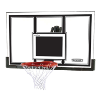
Slide U-bolt through backboard brackets for rim attachment.

Placing Brackets on Backboard

Place bracket assembly onto backboard, ensuring U-bolt rests in notches.

Securing Backboard Brackets

Secure backboard bracket assembly to backboard using hardware, finger tighten.

Attaching Rim to Backboard Bolts

Insert bolts through rim holes, secure with washers and T-nuts.

Securing Rim Assembly and Guard

Secure rim assembly and finger guard to backboard with hardware.

Sliding Compression Springs

Slide compression springs onto U-bolt, place retainer plate, and tighten nuts.

Backboard-to-Pole Assembly

Attaching Short Extension Arms

Secure short extension arms to backboard brackets with hardware.

Attaching Long Extension Arms

Secure long extension arms to backboard brackets with hardware.

Sliding Spacer into Spring

Slide spacer into counterbalance spring and attach to backboard brackets.

Tightening Hardware from Section 3.3

Tighten hardware from section 3.3 now for final assembly.

Securing Extension Arms to Pole

Attach short and long extension arms to pole assembly using hardware.

Handle Assembly

Securing Lifter Arm and Handle Grip

Secure lifter arm to extension arms, slide handle grip onto lifter arm.

Inserting Spacer into Cam

Insert spacer into plastic locking cam and attach cam to pole bracket.

Securing Bolt to Short Extension Arm

Secure bolt to short extension arm at the indicated location.

Stretching Counterbalance Spring

Raise backboard, stretch counterbalance spring over bolt.

Tightening All Hardware

Tighten all hardware now to complete the handle assembly.

Final Assembly

Backboard Preparation and Pad Attachment

Remove film and attach center frame pad to backboard.

Corner Pad and Net Attachment

Attach corner pads and net to the backboard and rim.

Filling Base with Sand (Option A)

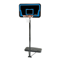
Fill base with sand using funnel, ensuring correct level and two adults.

Filling Base with Water (Option B)

Fill base with water, add bleach, ensuring correct level and two adults.

Adjusting System Height and Applying Sticker

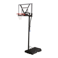
Adjust system height and apply height sticker to lifter arm.

Moving the System

Adjust system to lowest position, balance on wheels, and move carefully.

Maintenance and Care

Checking Hardware and Parts Wear

Check nuts, bolts, and parts for looseness, wear, or damage. Contact service for replacements.

Inspecting Warning Sticker

Inspect warning sticker for damage; request replacement if needed.

Checking for Rust and Repainting

Check pole sections for rust or chipped paint. Remove rust and repaint.

Warning Sticker Information

General Safety Warnings on Sticker

Follow warnings regarding hanging, face proximity, sliding, base filling, moving parts, and jewelry.

Base and Material Precautions

Ensure base is filled correctly, on smooth surface, and away from organic material.

Product Registration

5-Year Limited Factory Warranty

Warranty Coverage and Limitations

Covers defects in material/workmanship for 5 years; excludes misuse, installation, accidents, etc.

Warranty Exclusions and Usage

Excludes scratching, negligence, intentional damage, commercial use, and consequential damages.

Reporting Defects and Contacting Service

Report defects in writing with sales receipt and photos; contact Customer Service for assistance.

Related product manuals