Do you have a question about the Lifetime STREAMLINE BASKETBALL SYSTEM and is the answer not in the manual?
Explains the meaning of various icons used in the assembly instructions.
Provides crucial safety warnings and instructions for product operation and assembly.
Connects the top pole section to the middle section of the pole.
Aligns and inserts the top pole section into the middle pole section.
Slides the top pole section out and attaches hardware to the bottom.
Attaches the adjustment knob to the top and middle pole sections.
Aligns middle pole section with bottom pole section and inserts hardware.
Strikes the pole assembly end to properly seat sections; warns against hitting feet.
Inserts the rim into the backboard slots at a 45-degree angle.
Places the top pole between rim brackets and aligns holes with backboard.
Inserts carriage bolts through the rim, backboard, and into the top pole.
Secures rim to backboard and top pole using nuts and washers.
Secures rim brackets and braces to the top pole using hardware.
Inserts carriage bolts into backboard holes and secures with nuts.
Slides backboard brace onto bolts and secures with hardware.
Attaches other backboard braces to the backboard and rim brackets.
Attaches the cross tube to the bottom pole braces.
Fits the bottom pole brace assembly into the base recesses.
Attaches upper pole braces to the base and bottom pole brace assembly.
Inserts pole plug and attaches bottom pole braces and feet to the base.
Attaches upper pole braces to the bottom pole using hardware.
Inserts axles into wheels and slides washers onto both sides.
Places wheel assemblies under base indentations and steps on base to secure.
Attaches the net to the rim of the basketball hoop.
Fills the base with sand using a funnel and base plugs.
Fills the base with water, adding bleach to prevent algae.
Lists and illustrates all metal parts used in the assembly process.
Lists and illustrates all plastic parts used in the assembly process.
Lists and illustrates all hardware components required for assembly.
Guides adults on adjusting the system's height from 7.5 to 10 feet.
Instructions for safely moving the system using its wheels.
Details on checking hardware, wear, corrosion, and applying rust prevention.
Explains warnings for safe operation, including product use and maintenance.
Information on how to register the product and its benefits for customers.
Details the terms and conditions of the 5-year limited manufacturer's warranty.
| Brand | Lifetime |
|---|---|
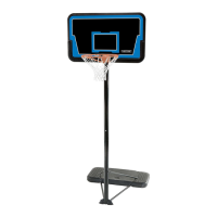
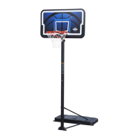
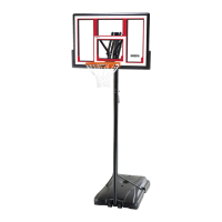
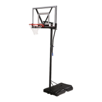
| Model | STREAMLINE BASKETBALL SYSTEM |
| Category | Sports & Outdoors |
| Language | English |