7.2. For model without reflector.
7.2.1. Put the couplings on the lamp.
7.2.2. Insert lamp(s) into the lampholders and lock it (them) by turning on 90°.
7.2.3. Twist the couplings on lampholders.
8. When regulated control gear is used, control wires polarity must follow label markings.
9. It is prohibited to place additional cables of through/mains wiring inside KRK luminaries to
avoid damage from control gear’s high temperature.
10. Check and control of emergency lighting can be done with «TELEMANDO TM» remote device
which supplied separately and can control group of luminaries (up to 35 units). Pressing "OFF"
button will switch off luminaire in emergency power state. Pressing "ON" button will simulate
emergency state activation.
11. The connection of TELEMANDO remote emergency check and control device should be done
with solid wire 1-1.5 mm cross-section and maximal length 250 m. The connections must be
made according the polarity shown on wiring diagram. The «+» terminal on the TELEMANDO
device should be connected to the «+»ТМ terminal on emergency power module, the «-» terminal
on the TELEMANDO device should be connected to the «-»ТМ terminal on emergency power
module.
These instructions assume expert knowledge corresponding to a completed professional
education as an electrician.
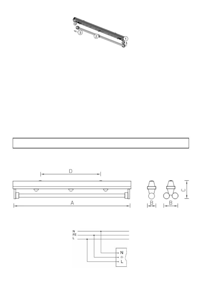
Overall and installation dimensions, mm
1. Mains connection scheme.