INSTRUCTIONSHEETNO.
INSTALLATION PROCEDURE FOR
LOW VOLTAGE
REFLECTOR TRIM IN THE 1000LV FRAME-IN KIT
lS:1052LV
0s90
Page 1 of 2
EAD AND UNDERSTAND THESE INSTRUCTIONS BEFORE INSTALLING FIXTURE.
his fixture is intsndsd for installation in accordance with the National Electrical Code or Iocsl regulations.
3 assure full compliance with local codes and regulations, check with your local electrical inepector before
wtallation. To prevent electrical shock, turn off electricity at fuse box before proceeding.
ietain these Instruction for maintenance referenc~
?~%~
FIG. B
FIG. C
FIG. D
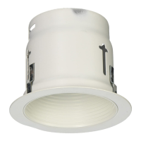
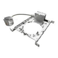
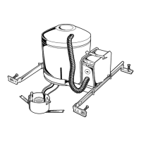
1. FRAME-IN
2. CLOSE4N
3, eNAP-ON
4. PuSH-UP
WARNING: BEFORE INSTALLING REFLEClOR TIRM TO FRAME4N KIT, READ MARKINGS IN REFLEClOR
TRIM AND fN SOCK~ CUP OF FRAME4N KIT TO DEf’ERMINE LAMP WAITAGE AND TYPE APPLICABLE FOR
YOUR lNSTALLATfON. IF IC. TYPE FRAME.fN KIT IS USED, IT MAY BE INSTALLED fN DIRECT CONTACT WITH
INSULATED CEILING. IF A NON IC. TYPE FRAME4N KIT IS USED, DO No INSTALL lNSULATfON WITHIN
3 INCHSS OF FIXWRE SIDES OR WIRING .COMPARTMENT, NOR ABOVE FfXTURE IN SUCH A MANNER AS ~
ENTRAP HEAT.
1. FRAME-IN (Fig. A)
4
r-.
See Frame-In Kit Instruction Sheet for installation
procedwe.
,–
FRAMINGKIT
MOUNTSFLUSH
!.;
!.
R~ATE RUIO-CLIPS (Fig. B)
,.,’
ON CEILINGMATERIAL
0“ \
As shown in Fig. E.
... $1...-
.. .. . . .
. . ..
: ,,..,.,,::.:,.;.
L SNARON (Fig. C).
Disconnect SOCKET from FRAME-IN KIT WIRES
CEILING
-.:.“.~.-:.
MATERIAL
by pulling off the insulated FEMALE
R~-CLIP “ “:-~~< ;
CONNECTORS. Insert FRAME-IN KIT WIRES with
POSITION
,., ,.
FEMALE CONNECTORS through %“ dia HOLE
on top of REFLECTOR TRIM. Reconnect SOCKET
FIG. E
(provided with REFLECTOR TRIM) by pushing
MALE CONNECTORS into FEMALE CONNECTORS
– SOCKETGUp
(Fig. G.)
*
LANCING
Engage TAB from SOCKET CUP into one of the
. . .
SLOTS on top of REFLECTOR TRIM and push
i“ HOLE
,* .
other end of SOCKET CUP with LANCING into
,=
TAe
the other
SLOT (Fig. F).
SLOTS ,}
REFLECTORTRIM
4. PUSH-UP (Fig. D).
Push REFLECTCR TRIM into ceiling until flange
FIG. F
SOCKET
is flush to ceiling (Fig. D).
INSULATINGSLEEVING
MALECONNECTORS
[Altachedto Sooketwires)
SEE BACK PAGE FOR LAMPING INSTALLATION
AND ADJUSTMENT.
FEMALEGONNECTORS
(Attachedto FixtureWires)
FIG. G
D-9 C31”ITC>I-I Is 1? :V:::::;,N:;::::,E:; :Y::