Do you have a question about the Lightware DVI-HDCP-OPTM-TX90 and is the answer not in the manual?
This document describes the DVI-HDCP-OPTM-TX90 and DVI-HDCP-OPTM-RX90, a pair of DVI-D fiber extenders designed to transmit DVI-D signals up to 240 m (790 ft) over one multimode fiber optic cable. These devices are ideal for extending high-resolution video signals in various professional and commercial environments.
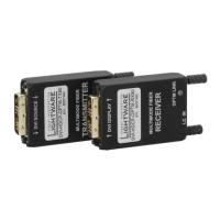
The DVI-HDCP-OPTM-TX90 (Transmitter) and DVI-HDCP-OPTM-RX90 (Receiver) work in tandem to extend DVI-D video signals. The transmitter converts the electrical DVI-D signal into an optical signal, which is then sent over a single multimode fiber optic cable. The receiver converts the optical signal back into an electrical DVI-D signal, allowing the extended video to be displayed on a monitor or projector.
A key feature of these extenders is their support for HDCP (High-bandwidth Digital Content Protection) pass-through. This ensures that protected content, such as Blu-ray movies or other copyrighted material, can be transmitted without any issues. The devices also support EDID (Extended Display Identification Data) emulation, which helps ensure compatibility between the source and display devices by providing the display's capabilities to the source.
The extenders are designed for single-fiber operation, meaning only one multimode fiber optic cable is needed for transmission. This simplifies installation and reduces cable clutter. The devices also feature a compact and lightweight design, making them easy to integrate into various setups.
The DVI-HDCP-OPTM extenders offer several usage features that enhance their functionality and ease of use:
Status LEDs: Both the transmitter and receiver units are equipped with status LEDs that provide visual feedback on the operational status. These LEDs indicate whether the unit is receiving power, if a DVI-D input signal is present, and if the optical link is established.
DVI-D Input/Output: The transmitter unit has a DVI-D input plug (24-pole DVI-D) for receiving the DVI-D/HDMI input signal from the source device. The receiver unit has a DVI-D output plug (24-pole DVI-D) for outputting the DVI-D/HDMI signal to the display device.
USB Micro-B Connector: Both units feature a USB micro-B connector for external powering of the extender. This provides flexibility in power options, especially when a power outlet is not readily available.
LC Optical Connector: The devices utilize an LC simplex receptacle for the fiber optic connection. This is a common and reliable connector type for multimode fiber applications.
Power Adaptor: The extenders can be powered using an external power adaptor (5V DC, 2A) with interchangeable AC power plugs (EU, UK, JP/US, AUS/NZ) and a locking DC connector. This ensures compatibility with various regional power standards and provides a secure power connection.
Mounting Options: The extenders come with an extender unit, a USB cable with interchangable plugs, and a USB micro-B cable. The extender unit can be mounted using screws, allowing for secure installation in various environments.
Maximum Extension Distances: The devices support different maximum extension distances depending on the resolution. For all resolutions, the maximum distance is 240 m (790 ft) over multimode fiber.
Connecting Steps: The manual provides clear instructions for connecting the devices:
The DVI-HDCP-OPTM extenders are designed for reliable operation with minimal maintenance. However, some general guidelines contribute to their longevity and performance:
Environmental Considerations: The devices are designed to operate within a specific temperature range (0° to +50°C) and humidity range (10% to 90%, non-condensing). Ensuring that the operating environment stays within these limits helps prevent damage and ensures optimal performance.
Cleaning: When cleaning the device, it is important to use a soft, dry cloth. Avoid using liquid or aerosol cleaners, as these can damage the device. Ensure that no flammable objects, such as candles, are placed on the apparatus.
Fiber Optic Cable Care: While the devices themselves require minimal maintenance, the fiber optic cable used for transmission is crucial. Handle the fiber optic cable with care to avoid kinks or damage, which can degrade signal quality. Keep the fiber optic connectors clean to ensure optimal signal transmission.
Firmware Updates: While not explicitly detailed as a user-maintenance feature, it's generally good practice to check for any available firmware updates from the manufacturer. Firmware updates can improve performance, fix bugs, and add new features.
Troubleshooting: The status LEDs provide valuable diagnostic information. If a problem occurs, observing the LED behavior can help identify the issue, such as a missing input signal or a broken fiber link. The manual also provides contact information for further technical support if needed.
WEEE (Waste Electrical & Electronic Equipment) Correct Disposal of This Product: This marking indicates that the product should not be disposed of with other household wastes at the end of its working life. To prevent possible harm to the environment or human health from uncontrolled waste disposal, users should separate this from other types of waste and recycle it responsibly to promote the sustainable reuse of material resources. Household users should contact either the retailer where they purchased this product, or their local government office, for details of where and how they can take this item for environmentally safe recycling. Business users should contact their supplier and check the terms and conditions of the purchase contract. This product should not be mixed with other commercial wastes for disposal.
By following these guidelines, users can ensure the long-term reliability and optimal performance of their DVI-HDCP-OPTM extenders.
| Signal Type | DVI |
|---|---|
| HDCP | Yes |
| Power Supply | 5V DC |
| Input Connector | DVI-D |
| Supported Resolutions | Up to 1920x1200 |
| Maximum Transmission Distance | 100m |