EasyManua.ls Logo

Lilytech ZL-6231A - User Manual

Lilytech ZL-6231A
4 pages
Print Icon
To Next Page IconTo Next Page
Loading...
Suzhou Lily Tech. Co., Ltd.
Page 1, Total 4 Pages
ZL-6231A Temperature Controller
Instruction Manual Version 1.2
Introduction
ZL-6231A thermostat is for cooling or heating control, with IP65 front panel, buzzer beeping and warning function.
There is a multifunction timer which is for incubator air exhaustion, or egg tray turning, or other application.
Main Specification
Power supply: 185~245Vac, 50/60Hz
Sensor: NTC, wire length is 2 meters
Output: 10A, 250Vac resistance
Setting range: -40~120
Display range: -40~130
Working: -10~45, 5~90%RH without dew
Dimension: W78 x H34.5 x D71 (mm)
Installation drilling: W71 x H29 (mm)
Case materials: PC + ABS fire proof
Protection level: IP65 (Front side only)
Keypad and Display
Icon Function On Off Blinking
R1 output R1 Temp. Output energized R1 Temp. Output de-energized Within protecting delay
Work mode Cooling mode Not in cooling mode Setting set-point
Work mode Heating mode Not in heating mode Setting set-point
Maintenance ---- No failure Has failure
Warning ---- No warning Has warning
R2 output R2 energized R2 de-energized
Egg turn times reached After reached, stop egg turn
Display
Remark
E01 Sensor failure (short or open)
Hi Room temp. is higher than the high limit
Lo Room temp. is lower than the low limit
EE Memory error
Err Password error
i
i
A
A
E
E
x
x
t
t
e
e
r
r
n
n
a
a
l
l
w
w
a
a
r
r
n
n
i
i
n
n
g
g
U
U
n
n
L
L
Parameters Will restore to factory default settings
Power up Display
The model (ZL-6231A) and software version (Version 1.1) will display successively: “6231”, “A 1.2”.
Operation
Set Set-Point (Factory Default Setting = 37.8)
KeepSdepressed for 3 seconds to enter into the status. The current set-point value displays.
Pressor to set the value (keeping depressed can fast set).
PressSto exit, and save the settings.
The status will exit, and the setting will not be saved, if no key operation within 30 seconds.
Set System Parameters
KeepPdepressed for 3 seconds, digits show “---0”.
Pressto select the digit of the password, pressto set the value of the digit.
PressS to confirm:
If the password is correct, enter into the parameter setting status, else display “Err”, and exit.
Set in parameter setting status:
Question and Answer IconNeed help?

Do you have a question about the Lilytech ZL-6231A and is the answer not in the manual?

Summary

Introduction

Main Specification

Keypad and Display

Power up Display

Displays the model number and software version successively on startup.

Operation

Set Set-Point

Procedure to adjust the temperature set-point using the keypad controls.

Set System Parameters

Procedure to access and modify system parameters using a password.

Parameter Code Table

Detailed list of configurable parameters, their codes, ranges, and default values.

Limit Protection

Conditions for R2 energizing based on temperature limits and set-points.

Control

Cooling Control

Operational logic for cooling mode based on temperature and timer settings.

Heating Control

Operational logic for heating mode based on temperature and timer settings.

Temp. Output Load Delay Protection

Protects output by delaying energization after power or de-energization.

Buzzer Function

Describes buzzer behavior for key presses, confirmations, and errors.

Over Temperature Warning

Conditions for displaying warning and buzzing due to exceeding temperature limits.

External Warning Input

Configuration and behavior of external warning input signals.

Sensor Fail

Action taken when a sensor failure (short or open) is detected.

Sensor Calibration

Method to calibrate the temperature sensor using parameter U20.

Restore to Factory Default Settings

Procedure to reset all settings to their factory default values.

Installation

Mounting Procedure

Step-by-step instructions for physically installing the controller into a mounting hole.

Attention

Electrical Wiring

Overview

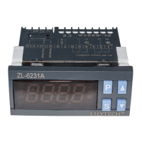
The ZL-6231A is a temperature controller designed for both cooling and heating applications. It features an IP65-rated front panel, a buzzer for audible alerts, and warning functions. A notable feature is its multifunction timer, which can be used for tasks such as incubator air exhaustion, egg tray turning, or other time-based applications.

Technical Specifications:

  • Power Supply: 185~245Vac, 50/60Hz
  • Sensor: NTC type, with a 2-meter wire length
  • Output: 10A, 250Vac (resistive load)
  • Setting Range: -40~120°C
  • Display Range: -40~130°C
  • Operating Conditions: -10~45°C, 5~90%RH (non-condensing)
  • Dimensions: W78 x H34.5 x D71 mm
  • Installation Drilling: W71 x H29 mm
  • Case Materials: PC + ABS fire-proof
  • Protection Level: IP65 (Front side only)

Usage Features:

The controller's operation is managed through a keypad with specific icons for R1 output, R2 output, work mode (cooling/heating), maintenance, warning, and egg turn times reached. The display shows various status indicators and error codes, including:

  • E01: Sensor failure (short or open)
  • Hi: Room temperature higher than the high limit
  • Lo: Room temperature lower than the low limit
  • EE: Memory error
  • Err: Password error
  • ¡A: External warning
  • UnL: Parameters will restore to factory default settings

Upon power-up, the device displays its model ("6231") and software version ("A 1.2").

Setting Set-Point:

To set the temperature set-point, press and hold the 'S' button for 3 seconds. The current set-point value will be displayed. Use the '▲' or '▼' buttons to adjust the value (holding them down allows for faster adjustment). Press 'S' again to exit and save the settings. If no key operation occurs within 30 seconds, the status will exit without saving. The factory default set-point is 37.8°C.

Setting System Parameters:

To access system parameters, press and hold the 'P' button for 3 seconds. The display will show "---0". Use the '▲' button to select the digit of the password and set its value. Press 'S' to confirm. If the password is correct, the device enters parameter setting status; otherwise, it displays "Err" and exits.

Within the parameter setting status, use '▲' or '▼' to select parameter codes. Press 'S' to display the value of the selected code, then use '▲' or '▼' to adjust it. Press 'S' again to return to parameter code selection. To exit and save all settings, press and hold 'P' for 3 seconds. Similar to set-point setting, if no key operation occurs within 30 seconds, the status will exit without saving.

Key Parameters:

  • U10 (Minimum time for Temp. Output to keep de-energized): 0-100 min (cooling only). Default: 0.
  • U20 (Sensor calibration): -9.9~+9.9°C. Default: 0.0.
  • U22 (Hysteresis for temperature control): 0.1~+10.0°C. Default: 0.1.
  • U40 (Timer period 1, time unit): 0 (sec), 1 (min), 2 (hour). Default: 0.
  • U41 (Timer period 1, time): 1-9999 (R2 on). Default: 30.
  • U42 (Timer period 2, time unit): 0 (sec), 1 (min), 2 (hour). Default: 1.
  • U43 (Timer period 2, time): 1-9999 (R2 off). Default: 60.
  • U44 (R2 working mode): 1 (Timer output), 2 (Timer output + limit_protection). Default: 2.
  • U45 (Timer repeat times): 0-9999 (0: never stops, else: R2 never on when U46 reaches U45). Default: 0.
  • U46 (Timer counter): 0-9999 (value saved to permanent memory hourly, clears to 0 before every hatching). Default: 0.
  • U52 (Over temp. warning delay): 0-180 min. Default: 0.
  • U53 (1st over temp. warning delay after power supplied): 0-180 hour (0: disable). Default: 0.
  • U54 (Temp. up limit (relative value)): 0.0~120.0°C (Absolute point = Set-point + U54). Default: 0.2.
  • U55 (Temp. low limit (relative value)): 0.0~120.0°C (Absolute point = Set-point – U55). Default: 37.8.
  • U60 (External input warning mode): 0-4 (0: disable, 1: NO locked, 2: NO unlocked, 3: NC locked, 4: NC unlocked). Default: 0.
  • U61 (Delay for external input warning): 0-120 min. Default: 0.
  • U62 (Buzzing warning): 0 (no warning), 1 (enable warning). Default: 0.
  • U90 (Control mode): CO (cool), HE (heat). Default: HE.
  • U99 (Password): 0000-9999 (0000 equals no password). Default: 0000.

Limit Protection (When U44 = 2):

  • Heating Mode (U90 = HE): If room temperature (Troom) ≥ Set-point + U54, then R2 will be energized.
  • Cooling Mode (U90 = CO): If Troom ≤ Set-point - U55, then R2 will be energized.

Control Logic:

  • Cooling Control (U90 = CO):
    • Temperature Control: If Troom ≥ Set-point + U22, and Temp. Output has been de-energized for U10, then Temp. Output energizes. If Troom ≤ Set-point, then Temp. Output de-energizes.
    • Temp. Output Load Delay Protection: After power supply, Temp. Output can be energized after U10. After Temp. Output de-energizes, it can be energized again after U10.
  • Heating Control (U90 = HE):
    • Temperature Control: If Troom ≤ Set-point - U22, then Temp. Output energizes. If Troom ≥ Set-point, then Temp. Output de-energizes.

Buzzer Function:

  • A short beep occurs with every key press.
  • A long beep occurs with every confirmation key press.
  • Three short beeps occur with every error operation.
  • Continuous buzzing occurs during failure or external warning input (if U62 = 1; no buzzing if U62 = 0). The warning stops if 'P' is pressed or the warning condition disappears.

Over Temperature Warning:

When Troom ≥ SP + U54 or Troom ≤ SP – U55, a warning is displayed, and the buzzer activates.

External Warning Input:

  • NO (Normal Open): Open means no warning; closed means warning.
  • NC (Normal Close): Closed means no warning; open means warning.
  • Locked: Warning persists after the external warning disappears. Press 'P' to stop the warning.
  • Unlocked: Warning stops after the external warning disappears.
  • Note: When an external warning is active, the output(s) will be de-energized.

Maintenance Features:

Sensor Fail:

If the sensor fails, R1 output stops energizing.

Sensor Calibration:

The sensor can be calibrated using parameter U20.

Restore to Factory Default Settings:

To restore all settings to factory defaults, press and hold 'P' and '▲' simultaneously for 5 seconds. A beep will sound, and "UnL" will display. Press '▲' or '▼' twice, another beep will sound, and all settings will be restored.

Installation:

  1. Insert the controller into the drilling hole.
  2. Clamp the controller in place.

Attention for Wiring:

  • Wiring should be performed by certified technicians.
  • Incorrect connections can damage the controller and loads. Power supply to terminals 7 and 8 should be checked first. A multimeter can be used to check outputs and inputs with the help of settings.
  • Sensor and input signal wires should not be laid together with power supply wires or in the same pipe.
  • Sensor wire should be as short as possible and not wound to avoid electrical noise.
  • Loads must be within the controller's output driving ability. When using AC/DC modules, tungsten lamps, or motors as loads, specific requirements must be met to prevent surging current damage or shorten output lifespan:
    • AC/DC Module: Rated current no more than 1/10th of output specification under pure resistance.
    • Tungsten Lamp: Rated current no more than 1/15th of output specification under pure resistance.
    • Motor: Rated current no more than 1/5th of output specification under pure resistance.
    • For example, driving a 1500W tungsten lamp with a 7A (pure resistance spec.) relay will immediately burn the relay contactor.
  • Do not touch internal components.
  • Avoid installing the controller in environments with humidity over 90%RH, dew, vibration, shock, possible spray, erosive air, or explosive air.

Lilytech ZL-6231A Specifications

General IconGeneral
BrandLilytech
ModelZL-6231A
CategoryThermostat
LanguageEnglish

Related product manuals