Do you have a question about the Lincoln Electric Invertec V275-S and is the answer not in the manual?
| Brand | Lincoln Electric |
|---|---|
| Model | Invertec V275-S |
| Category | Welding System |
| Language | English |
Warnings regarding chemicals in engine exhaust known to cause cancer or birth defects.
Safety precautions for operating equipment powered by an engine.
Information on potential health effects and precautions related to EMF fields from welding.
Details on how to prevent electric shock while operating welding equipment.
Information on protecting against the harmful effects of arc rays.
Precautions regarding hazardous fumes and gases produced during welding operations.
Precautions to prevent fires and explosions caused by welding sparks.
Safety guidelines for handling compressed gas cylinders to prevent explosions.
Safety measures for electrically powered welding equipment.
Detailed technical specifications including input/output ratings, dimensions, and temperature ranges.
Recommended wire gauges and fuse sizes for different input voltages.
Dimensions and weight of the Invertec V275-S unit.
Operating and storage temperature ranges for the Invertec V275-S.
Critical safety warnings and precautions to follow during equipment installation.
Guidelines for choosing an appropriate and safe location for the Invertec V275-S.
Instructions on stacking, tilting, and locating the machine to prevent toppling and interference.
Guidance on proper input power connections, requiring a qualified electrician.
Step-by-step guide to changing the machine's input voltage configuration.
Details on connecting welding cables to output terminals and selecting cable sizes.
Instructions for assembling and installing quick disconnect plugs for welding cables.
Safety warnings and precautions specific to operating the welding machine.
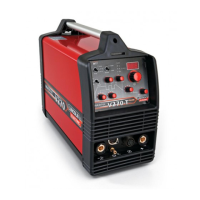
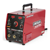
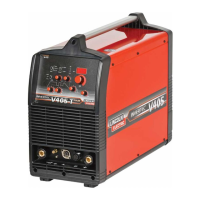
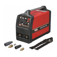
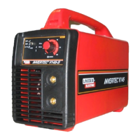
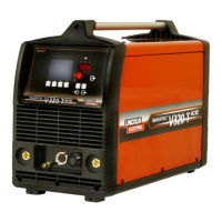
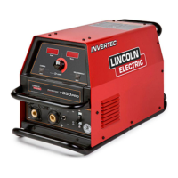
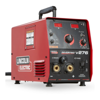
Overview of the Invertec V275-S, its capabilities, and intended use.
Description of key operational features like current adjustment and arc control.
Information on machine's current ratings, duty cycles, and any limitations.
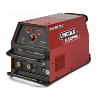
Explanation of the controls and settings on the front panel of the Invertec V275-S.
How to use the power switch to energize the machine.
Explanation of how to adjust the output current using the control knob.
How to select between local machine control or remote control.
Description of the mode switch for selecting welding processes like SMAW and GTAW.
Explanation of the Hot Start feature for improved arc starting in SMAW.
How to use the Arc Force control to adjust arc characteristics.
Details about the output terminals, remote receptacle, and indicators.
Details on Manual Arc Welding (Stick), Air Carbon Arc Cutting, and TIG Welding.
Information on Parallel Operation, Overload Protection, Thermal Protection, Fan, and Power-Up Sequence.
Description of the remote output control box and available cable lengths.
Details on Twist-Mate cable plugs and receptacles for connecting welding cables.
Accessories specifically for TIG welding applications, including torch adapters and amptrols.
Accessories and kits for stick welding.
Critical procedure to safely discharge capacitors before performing maintenance.
Recommended routine maintenance tasks to be performed every six months.
Instructions on how to effectively use the troubleshooting guide provided in the manual.
Procedures for troubleshooting and replacing printed circuit (PC) boards.
Troubleshooting steps for issues related to the machine's output.
Troubleshooting steps for issues related to welding performance and arc stability.
Wiring diagram for specific code numbers of the Invertec V275-S.
Electrical diagrams for different models of the Invertec V275-S.
Wiring diagram specific to the Invertec V275-S unit.
Electrical diagrams for specific code numbers of the Invertec V275-S.