Do you have a question about the Lincoln Electric INVERTEC V320-T AC/DC and is the answer not in the manual?
| Brand | Lincoln Electric |
|---|---|
| Model | INVERTEC V320-T AC/DC |
| Category | Welding System |
| Language | English |
General warnings about hazards, responsibilities, and reading the manual.
Covers risks of electric shock and safe handling of powered equipment.
Addresses dangers from fumes, gases, arc rays, sparks, and hot materials.
Warns about EMF interference and notes CE compliance.
Explains the safety mark for environments with increased electric shock risk.
Specifies suitable operating locations and environmental conditions.
Details on connecting the machine to the power source.
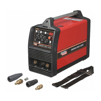
Instructions for connecting welding cables for different processes.
Procedure for connecting cables for Stick welding.
Procedure for connecting cables for TIG welding.
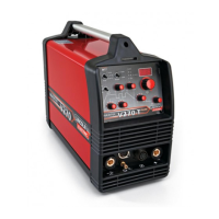
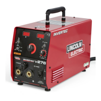
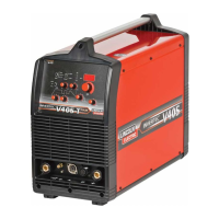
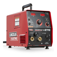
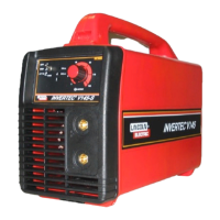
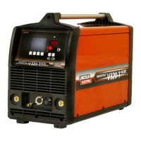
Description of controls on the rear panel, including power switch.
Details on the dynamic LCD display, status LEDs, and push buttons.
Explanation of the different sections within the dynamic LCD display.
Describes how to interpret and adjust weld sequence diagrams.
Explains the parameter display, icons, and adjustment methods.
Details the different welding modes selectable via push button A.
Explains the trigger modes available for TIG welding.
Step-by-step operation for the 2-step TIG trigger mode.
Step-by-step operation for the 4-step TIG trigger mode.
How to use bi-level current settings via setup menu.
Enables spot welding with adjustable time parameters.
Selection between local and remote operation for stick welding.
Enabling and disabling pulse welding for TIG mode.
Saving and recalling welding parameters using memory functions.
Automatic sensing of remote devices for TIG operation.
Lists and describes parameters adjustable on the V320-T AC/DC.
Explains how to access and navigate the user setup menu.
Details parameter symbols, selection options, and default values.
Lists parameter numbers and their corresponding descriptions.
Function to set initial start energy limit for AC TIG.
Guidelines for maintenance and repair operations.
Procedure for safely discharging internal capacitors.
Information on EMC design, potential disturbances, and mitigation.
Details on rated input current, voltage, and output characteristics.
Specifies the operational welding current range.
Guidance on selecting appropriate input cables and fuses.
Provides physical dimensions and temperature operating ranges.