Page Number - 4
Form 403626
FlowMaster™ Rotary Driven Hydraulic Pump
A
F
G
H
J
B
D
E
C
K
L
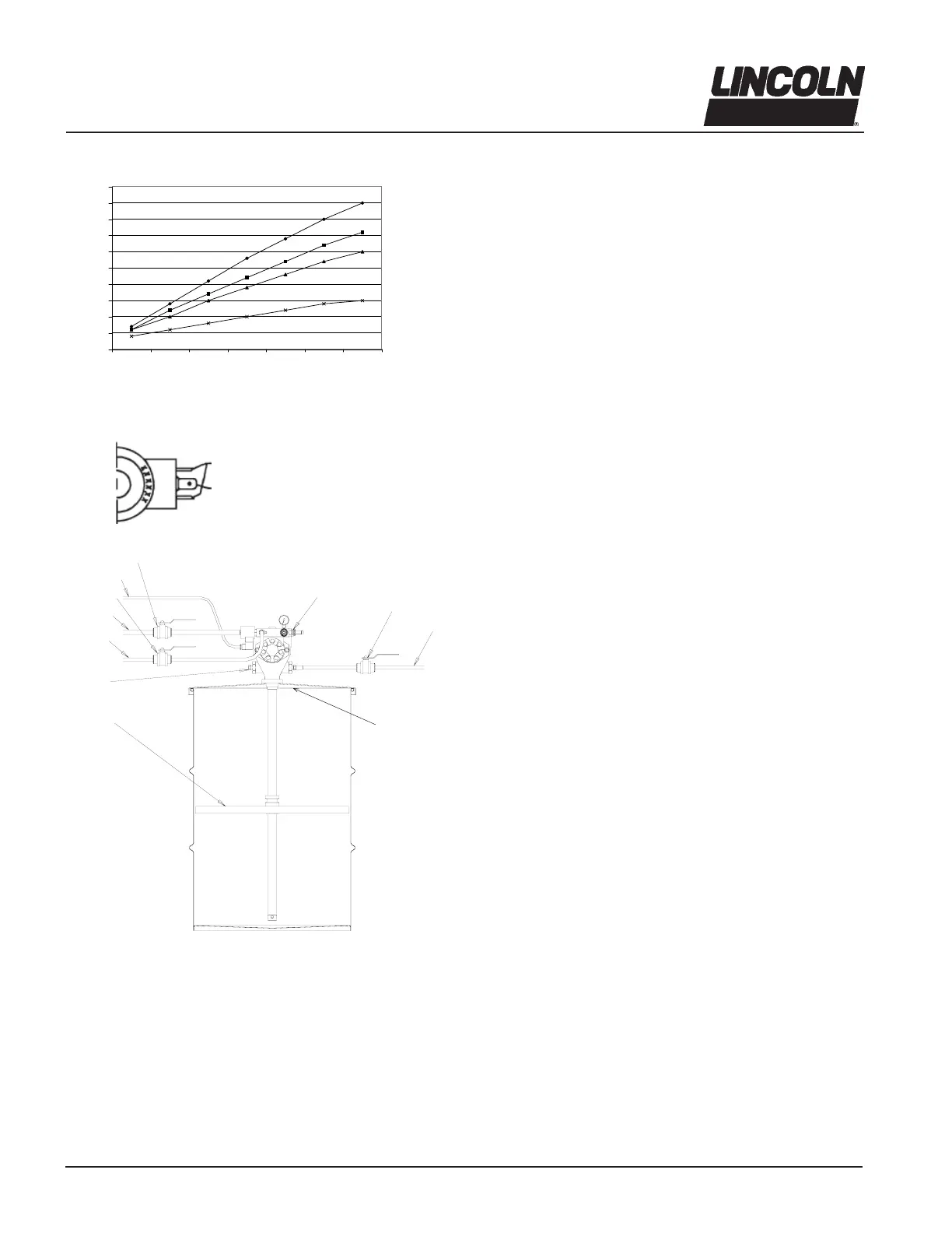
A - Pump Outlet Plug
B - Hydraulic Supply Line
C - Hydraulic Return to Tank
line (3/4” ID min.)
D - Supply Line Shut-off Valve
E - 24 VDC from Controller
F - Return Line Shut-off Valve
(3/4” ID min.)
G - Vent Valve Port with Restrictor
H- Outlet Shut-off Valve
J - Material Supply Line
K - Follower Plate (85492 for 120 lb. drum only)
L - Drum Cover (83115 for 400 lbs., 84616 for 120 lbs.)
Illustration 2
Installing the Pump
Typical installation is shown only as a guide for selecting and
installing system components. Contact your Lincoln
Industrial representative for assistance in designing a
system to suit your specifi c needs.
The pump was tested in light weight oil which was left in to
protect the pump from corrosion. Flush the pump before con-
necting it to the system to prevent contamination of the grease
with residual oil.
The pump has fl ow and pressure controls integrated into the
manifold (76). A normally closed ON/OFF Solenoid Valve (74)
is also integrated into the manifold and will start or stop the
pump operation.
1. Mount the pump securely on the drum cover so that it
cannot move or vibrate during operation.
2. Attach hydraulic supply line to the Inlet and return line to
the Tank ports.
3. Connect material supply line to the pump outlet. Plug
the unused outlet on opposite side of the pump.
4. Install high pressure shut-off valve in the material supply
line. (Required)
5. Connect 24 VDC power supply to the solenoid valve (74).
See Illustration #1. Use connector plug (75) supplied
with the pump.
NOTE: To install the pump Model 85481 as a replacement
pump for 84961 used on Model 84944, use adapter/spacer kit
p/n 272013 with bolts p/n 50014, included in the pump pack-
age (see illustration #4).
24VDC Connections
No Connection to
Center Lug
Solenoid Valve
Grease Output vs Hydraulic Input
0
5
10
15
20
25
30
35
40
45
50
1234567
Hydraulic Flow Input (g/m)
Grease Output (inches³/min.)
80°F (27º C)
20°F (-7º C)
0°F (-18º C)
-20°F (-29º C)
To order call 1-800-548-1191 or visit www.partdeal.com - info@partdeal.com
 Loading...