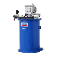
The FlowMaster Rotary Driven Electric Pump, available in models 85598 (400#) and 85599 (120#) and designated as Series "A," is a robust and efficient lubrication pump designed for centralized lubrication systems. This device utilizes a rotary driven electric motor to generate high grease pressure, making it suitable for various industrial applications.
Function Description
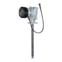
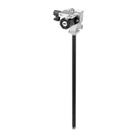
The FlowMaster pump operates on a 120/230 VAC dual voltage electric motor, which drives a single-stage planetary gear system. The rotary motion from the electric motor is converted into reciprocating motion through an eccentric crank mechanism. This reciprocating action causes the pump cylinder to move up and down, making it a positive displacement double-acting pump. Grease output occurs during both the up and down strokes.
During the down stroke, the pump cylinder extends into the grease. Through a combination of shovel action and vacuum generated in the pump cylinder chamber, grease is forced into the pump cylinder. Simultaneously, grease is discharged through the pump's outlet. The volume of grease taken in during intake is twice the amount of grease output during one cycle. During the upstroke, the inlet check closes, and one half of the grease taken in during the previous stroke is transferred through the outlet check and discharged to the outlet port. The pump's grease output is directly proportional to its RPM.
This pump is primarily designed for centralized lubrication systems, including Single Line Parallel, Single Line Progressive, and Two Line systems, ensuring efficient and consistent lubricant delivery to multiple points.
Important Technical Specifications
- Models: 85598 (400#) and 85599 (120#)
- Voltage: 120/230 VAC (dual voltage motor)
- Frequency: 50/60 Hz
- Maximum RPM: 360 RPM
- Maximum Outlet Pressure: 5,000 PSI
- Operating Temperature: -40 to +150 °F (-40 to 65 °C)
- Pump Outlets: 1/4 NPTF
- Weight: 50 lbs (23 kg)
- Gear Ratio: 5:1
- Cubic In/Min (at 1000 psi Backpressure, NLGI #1 Grade Grease):
- 80 °F (27 °C): 6.7
- 40 °F (4 °C): 6.4
- 20 °F (-7 °C): 6.1
- Dimensions (Model 85598):
- DIM "A": 34.0 in (864 mm)
- DIM "B": 42.85 in (1088 mm)
- Dimensions (Model 85599):
- DIM "A": 27.5 in (699 mm)
- DIM "B": 36.86 in (936 mm)
- Patent Information: U.S. Patent No. 6,102,676, Foreign Patent Pending.
Usage Features
- Installation: The pump must be securely mounted on the drum cover to prevent movement or vibration during operation. A material supply line should be connected to the pump outlet, and a Safety Unloader Valve (e.g., 272722) must be installed on the opposite side of the pump outlet to ensure the maximum pressure remains below 5,000 PSI. A high-pressure shut-off valve is also required in the material supply line. Power supply (120 VAC or 230 VAC) is connected to the solenoid valve, and the motor must be wired for the proper line voltage and fused as recommended. An auxiliary motor mount is necessary for AC motors.
- Initial Operation: Before connecting to the system, the pump should be flushed to remove any residual light-weight oil used for corrosion protection during testing. To start, remove the pump outlet line, energize the pump with a full lubricant container, and ensure all air is expelled and even lubricant flow is achieved before reattaching the outlet line.
- Lubricant Management: It is crucial never to allow the pump to run dry of lubricant. The supply lubricant level should be monitored and refilled as necessary to prevent damage and ensure continuous operation.
- Safety Precautions: The equipment generates very high grease pressure. Extreme caution is advised to prevent fluid injection through the skin or splashing into the eyes. Adequate protection is recommended. If fluid penetrates the skin, immediate emergency medical care is necessary. Always install a relief valve to keep pump pressure below 5,000 PSI and use high-pressure components.
- Upgraded Design (July 2008): Newer versions of the FlowMaster pump incorporate several improvements for enhanced performance and longevity:
- Bushing and plunger seals, along with elastomer cup seals, for longer life and better high-temperature operation.
- A crankcase oil dipstick for easier oil level monitoring.
- Hardened and ground sections on the reciprocating tube for extended life and improved crankcase oil control.
- Hardened and ground pivot pin bushings with a tighter fit into the pivot pin anchor.
- An improved pivot pin fastener with a deeper Allen hex socket.
All improved parts are backward compatible with older models.
Maintenance Features
- General Safety: Before servicing or repairing the pump, relieve all hydraulic and outlet pressure to reduce the risk of injury from injection, splashing fluid, or moving parts. Only Lincoln Industrial parts should be used for service and repair.
- Crankcase Oil Service:
- Check Oil Level: After every 750 hours of machine operation or monthly. The oil level should be at the middle of the crankshaft (indicated by a dot on the dipstick).
- Change Oil: After every 2,000 hours of machine operation or annually.
- Oil Type: Use SAE 10W30 motor oil for ambient temperatures between -40 to 150 °F (-40 to 65 °C). For ambient temperatures between 50 to 70 °F, Mobil Arrow HFA Low Temperature oil is recommended. The crankcase holds 15 oz. of 10W30 motor oil.
- Troubleshooting: The manual provides a comprehensive troubleshooting guide for common issues such as the pump not running, erratic operation, low output, leakage, noise, or failure to build pressure. This guide helps identify possible causes (e.g., seized pump, low grease level, worn components, lack of crankcase oil, foreign material) and suggests corrective actions (e.g., refill reservoir, replace seals, add oil, dismantle and repair).
- Repair and Disassembly/Assembly Procedures: The manual includes detailed, step-by-step instructions with accompanying images for disassembling and reassembling various pump components. This includes:
- Removing the gearbox assembly, motor, shaft coupler, and adaptor shaft.
- Draining crankcase oil and removing bearing covers.
- Extracting the pump shaft, outlet pin nuts, and housing tube components.
- Disassembling the pump element, bronze bushing, and oil seals.
- Removing crankrod and eccentric assembly, wrist pin bushings, and plunger tube components.
- Disassembling check seat housing, ball cage, check ball, and check spring.
- Removing flat head screws, counterbalance weights, and retaining rings from the crankrod/eccentric assembly.
- Instructions for installing O-rings and backup washers correctly.
- Special Tools: Specific tools are required for maintenance and repair, including various open-end and Allen wrenches, sockets, screwdrivers, snap ring pliers, and a special tool kit (276275) which includes steel pipes and nylon rods for component removal.
- Torque Specifications: Reassembly instructions include precise torque specifications for screws and nuts (e.g., gearbox mounting screws: 20-25 Ft. Lbs.; motor mounting screws: 100-110 in. lbs.; outlet pin nuts: 30-35 Ft. Lbs.).
- Seal and Gasket Replacement: Recommendations are provided for replacing O-rings, cup seals, backup washers, and gaskets during reassembly to ensure proper sealing and prevent leaks. Loctite 242 (medium strength thread lock) or equivalent is recommended for screw threads and plunger tube threads.
- Repair Kits: A repair parts list and repair kit selection chart are provided, detailing common and non-common items, their part numbers, and the corresponding repair kits for Series A and Series B pumps. This facilitates ordering the correct parts for specific repairs. For instance, kits like 275186 (Upper Bushing & Plunger Kit) and 275187 (Lower Bushing & Plunger Kit) are available for specific component groups.
- Warranty and Service: Annual inspection by a factory-authorized warranty and service center is recommended. Contact information for Lincoln Industrial representatives and service centers is provided for assistance with system design, repair, or adjustments beyond those specified in the manual.