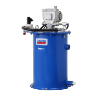
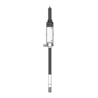
The FlowMaster II rotary driven hydraulic pump series "A" is a fully hydraulically operated, adjustable grease pump designed for centralized lubrication systems. It is suitable for single-line parallel, single-line progressive, and two-line systems. The pump's grease output is proportional to the hydraulic input flow and is affected by temperature.
Function Description:
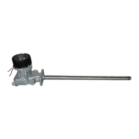
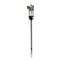
The pump is driven by the rotary motion of a hydraulic motor, which is converted into reciprocating motion through an eccentric crank mechanism. This reciprocating action causes the pump cylinder to move up and down. The unit operates as a positive displacement double-acting pump, meaning grease output occurs during both the up and down strokes. During the downstroke, the pump cylinder extends into the grease, and through a combination of shovel action and vacuum generated in the pump cylinder chamber, grease is forced into the pump cylinder. Simultaneously, grease is discharged through the pump's outlet. The volume of grease taken in during intake is twice the amount of grease output during one cycle. During the upstroke, the inlet check closes, and half of the grease taken in during the previous stroke is transferred through the outlet check and discharged to the outlet port. An integrated pump control manifold manages input flow and pressure, and a 24 V solenoid valve is incorporated to turn the pump on and off.
Important Technical Specifications:
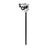
The FlowMaster II series includes models 85731 (5 U.S. gallons), 85732 (60 lbs / 27 kg), 85733 (120 lbs / 54 kg), 85734 (400 lbs / 181 kg), 85138 (400 lbs / 181 kg), and 85144 (CAT branded). The main difference between these models is the length of the housing tube.
Key pump specifications include:
- Hydraulic inlet flow: 2 U.S. gpm (7.6 liters/min)
- Operating temperature: -40 to 150 °F (-40 to 65 °C)
- Operating working hydraulic pressure: 300 psi (21 bar)
- Solenoid voltage: 24 V
- Hydraulic inlet port: SAE 4
- Tank return port: SAE 6
- Maximum supply inlet hydraulic pressure: 3,000 psi (206 bar)
- Pump outlets: 1/4 in NPTF
- Maximum hydraulic fluid temperature: 250 °F (121 °C)
- Pump ratio with manifold: 10:1
The pump dimensions vary by model, primarily in Dimension A (overall length) and Dimension B (housing tube length). For example, model 85731 has Dimension A of 25.08 in (637 mm) and Dimension B of 13.74 in (349 mm), while model 85734 has Dimension A of 45.40 in (1153 mm) and Dimension B of 34.06 in (865 mm).
Usage Features:
- Installation: The pump should be securely mounted on a drum cover to prevent movement or vibration. Hydraulic supply and return lines must be attached to the inlet (SAE 4 ORB) and tank ports (SAE 6 ORB), respectively. A material supply line connects to the pump outlet (1/4 in NPTF), and any unused outlets should be plugged. A high-pressure shut-off valve is required in the material supply line. The 24 V power supply connects to the solenoid coil using the provided plug.
- Operation: Before connecting to a system, the pump should be flushed to prevent contamination, as it is tested with lightweight oil for corrosion protection. The pump is factory-set at 320 psi (22 bar) working inlet hydraulic pressure with a flow rate of 2.5 gallons/min (9.5 liters/min). Users should not exceed 400 psi (27 bar) working hydraulic pressure and should always use the lowest pump output pressure and hydraulic fluid flow to achieve desired results to reduce pump wear.
- Pressure and Flow Control: The pump manifold includes integrated flow and pressure controls. The pressure control valve (70) and flow control valve (69) can be adjusted to meet specific application requirements. Pressure adjustment involves turning the hex head adjustment screw counter-clockwise until it stops (minimum pressure setting of about 100 psi / 6 bar), then clockwise until the desired pressure is reached on the manifold pressure gauge (64). Flow adjustment involves loosening and removing the hex head cap from the flow regulator (69), then turning the hex head screw clockwise to reduce flow or counter-clockwise to increase it. The recommended flow control valve setting is 1/4 turn counter-clockwise.
- Safety: Operators must wear personal protective gear, including eye protection, and fully understand all safety warnings and instructions. The equipment generates high pressure, and extreme caution is advised to prevent fluid injection injuries. Any fluid penetration of the skin requires immediate medical attention. The pump should not be operated dry of lubricant, as this can cause friction heat and damage seals. The maximum operating temperature for hydraulic fluid is 250 °F (121 °C).
Maintenance Features:
- Crankcase Oil Service Interval: The oil level should be checked monthly or after every 750 hours of machine operation. Oil should be changed annually or after every 2,000 hours of machine operation. SAE 10W30 motor oil (15 oz / 0.44 l) is recommended for ambient temperatures between -40 to 150 °F (-40 to 65 °C). Low-temperature oil should be used for ambient temperatures between 50 to 70 °F (10 to 21 °C). The oil level should be at the indicating dot on the dipstick (middle of the crankshaft).
- Inspection: Annual inspection by a factory-authorized warranty and service center is recommended. Specialized equipment and knowledge are required for pump repair. Any pump that appears damaged, badly worn, or operates abnormally should be removed from service and sent to an authorized service center for repairs.
- Disassembly and Assembly: The manual provides detailed instructions for disassembling and assembling various pump components, including the crank rod and eccentric, reciprocating tube, and the main pump assembly. This includes steps for removing and installing retaining rings, o-rings, bushings, seals, and other parts, often requiring special tools (e.g., tool kit 276275). Torque specifications are provided for critical fasteners, such as flat head screws (100 to 110 in-lbf / 11.3 to 12.4 Nm) and wrist pin anchor (20 to 25 ft-lbf / 27 to 34 Nm). Thread locker is recommended for certain threaded connections.
- Troubleshooting: A troubleshooting guide is included to address common issues such as the pump not running, running erratically, low output, leakage, noise, or failure to build pressure. Solutions range from checking electrical faults and hydraulic supply to replacing faulty components and performing detailed disassembly and repair procedures.