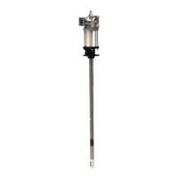
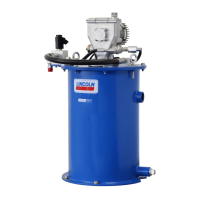
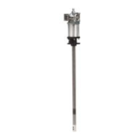
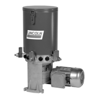
The Lincoln 83513, series "J" air-operated chassis pump is designed for pumping low and medium viscosity materials, specifically grease, from drums and pails. This robust pump is engineered for reliability and efficient operation in various lubrication applications.
Technical Specifications:
- Air Motor Effective Diameter: 2.5 inches (63.5 mm)
- Air Inlet: 1/4 inch NPTF
- Material Outlet: 1/4 inch NPTF
- Ratio: 50:1
- Delivery Output: 80 in³/minute (1 311 cm³/minute)
- Delivery per Cycle: 0.35 in³/cycle (5.7 cm³/cycle)
- Minimum Air Pressure: 30 psi (2 bar)
- Maximum Air Pressure: 150 psi (10 bar)
- Maximum Output Pressure: 7,500 psi (517 bar)
- Noise Level at 120 psi (8 bar): <85 dBA
Dimensions:
The pump has a compact design with an overall height of approximately 11 inches (279 mm) for the main body. The air motor section measures about 6 inches (152 mm) in width and 3 3/16 inches (81 mm) in depth. The pump tube extends approximately 18 7/8 inches (479 mm) below the main body, with a diameter of 1 inch (25 mm). The air inlet is 1/4 inch NPTF, and the lubricant outlet is also 1/4 inch NPTF. There are four threaded mounting holes (1/4 inch - 20) for secure installation.
Usage Features:
The pump is designed for ease of use and control. To start the pump, the main air supply is turned on, and the air regulator is slowly opened, regulating air pressure between 20-40 psi (1.4-2.8 bar) to prime the pump. The dispensing valve is then opened to purge air from the system, allowing the pump to cycle until grease, free of air pockets, flows from the valve. Once primed, the air pressure can be adjusted to achieve a smooth flow of grease.
It is crucial not to allow the pump to operate when out of material, as this can cause it to accelerate quickly and run too fast, leading to costly damage. If the pump accelerates quickly or runs too fast, it should be stopped immediately, and the grease supply should be checked and refilled if necessary.
For circulating systems, the pump runs continuously, slowing down or speeding up as supply demands, until the air supply is shut off. In direct supply systems, the pump starts when the gun or dispensing valve is opened and stalls against pressure when it is closed, provided there is adequate air pressure supplied to the motor. An air regulator is used to control pump speed and grease pressure, and it is recommended to always use the lowest pressure required to achieve desired results.
The manual emphasizes several safety precautions:
- Always read and understand all warnings, cautions, and instructions before operating the equipment.
- Extreme caution is advised to prevent personal injury and/or property damage from equipment misuse.
- Warning and instruction labels on the pump must be legible.
- The manual should be retained for future reference regarding warnings, operating, and maintenance instructions.
- Adequate personal protection (e.g., eye protection) is recommended to prevent splashing of material on skin or in eyes.
- The air coupler must ALWAYS be disconnected from the pump when it is not in use.
- Never exceed 90 psi (6 bar) air pressure when using whip hoses, which are rated at 4,500 psi (310 bar).
- The maximum working pressure of the lowest-rated component in the system must not be exceeded. The pump can develop 7,500 psi (517 bar) at 150 psi (10 bar) maximum incoming air pressure. All system equipment and accessories must be rated to withstand this maximum working pressure.
- Failure to comply with these warnings can result in serious injury or damage to equipment.
- During flushing with solvents, always hold a metal part of the dispensing valve firmly to the side of a grounded metal pail to reduce the risk of injury from splashing or static sparking. The pump should be operated at the lowest possible fluid pressure during this process.
- The pump or system should never be operated with pressure applied. A pressure relief procedure must be performed before and after operating the pump. This involves disconnecting the air supply, pointing the dispensing valve away from oneself and others, and opening the dispensing valve into a container until pressure is relieved. If pressure is not relieved, the dispensing valve or hose may be restricted, and the hose end coupling should be very slowly loosened, then completely loosened to clear the valve and/or hose.
- Do not use a pump that appears damaged. Contact a factory-authorized service center for repairs.
- Do not alter or modify any part of the equipment.
- Do not operate equipment with combustible fluids.
- Do not repair or disassemble equipment while the system is pressurized.
- Ensure all grease connections are securely tightened before use.
- Always read and follow grease manufacturer's recommendations regarding grease compatibility, protective clothing, and equipment.
- Regularly check all equipment and repair or replace worn or damaged parts immediately.
- Never point the dispensing valve at any part of the body or another person, nor try to stop or deflect material with hands or body.
- Always check equipment for proper operation before each use, ensuring safety devices are in place and working.
Maintenance Features:
Regular maintenance is essential for the longevity and efficient operation of the pump.
- An air line filter/regulator is recommended to remove harmful dirt and moisture from the compressor air supply.
- The air valve mechanism should be lubricated once a year. This involves disconnecting air, removing the cover screws, cover plate, and gasket, then removing and disassembling the air valve casting. The casting should be cleaned or flushed to remove foreign particles. Before replacing the toggle assembly, the cavity should be packed with approximately 1.5 oz. (44.4 ml) of NLGI 1 (light grade) water repellent grease. The cover gasket, plate, and screws are then replaced and tightened to avoid air leaks. Periodic inspection of parts at least once a year is advisable.
- To prevent material restriction, the system should be flushed as required with a compatible solvent to prevent material buildup when pumping materials that dry or harden.
- For corrosion prevention, the pump should never be left filled with water or air.
- If complete disassembly is required, a repair kit should be ordered, and all gaskets, o-rings, and packings should be replaced.
- When assembling, the air cylinder and air piston rod should be lubricated to prevent damage to the air piston packing and pump gland packing. The piston rod should be threaded through the gland packing when assembling.
- Before tightening the four valve seat bolts, align the valve slide seat and gasket, slide valve gasket, and air valve casting by placing a rod through the center hole. All fasteners should be started by hand to avoid stripping threads.
Troubleshooting:
The manual provides a troubleshooting guide for common issues:
- Air motor does not operate: Check air supply, check for broken trip rod, broken toggle or foreign object in priming tube, or check for rust, worn, or scored parts.
- Air seepage from air exhaust while pump is not operating: Check valve slide seat and gasket (58), trip rod packing (19), and gasket (17) for cuts or damage.
- Loss of pressure, volume, or continuous operation when not in normal use: Remove and clean lower inlet checks, check for foreign material, inspect sealing surfaces between upper and lower inlet checks, and replace if worn or pitted. Replace shovel rod if rough or pitted, and replace shovel rod packing (45). Inspect lubricant supply line for leaks or breaks.
- Lubricant leaking from weep hole in outlet casting: Replace o-ring (26) and u-cup (27). Ensure gland nut (21) is tight.
- Excessive amount of air in lubricant or excessive amount of lubricant coming from air exhaust: Replace gland packing (23), gland gasket (24), o-ring (26), and u-cup packing (27).
If these procedures do not correct the problem, a factory-authorized service center should be contacted. When submitting equipment for repair, the nature of the problem and whether a repair cost estimate is required should be stated.
Service Parts:
The manual includes a detailed list of service parts with item numbers, descriptions, quantities, and part numbers, facilitating easy identification and ordering of replacement components. Key components include the air motor piston rod, air piston packing, air cylinder gasket, trip sleeve, air valve casting, various gaskets, packings, springs, and the plunger and bushing assembly. A synthetic grease kit (245530) is available separately to convert the pump for compatibility with synthetic greases and lubricants. This kit includes FPM o-rings, TFE/FPM u-cups, and FPM solid packing.