EasyManua.ls Logo

Lincoln Impinger II Express Series User Manual

Lincoln Impinger II Express Series
48 pages
To Next Page IconTo Next Page
Page #1 background imageLoading...
Page #1 background image
P/N: L371076
REV: 10.19.09
Lincoln Foodservice Products, LLC
1111 North Hadley Road
Fort Wayne, Indiana 46804
Telephone: 260.459.8200
Fax: 888.790.8193
Technical Support: 800.678.9511
lincolnfp.com
PARTS & SERVICE MANUAL
Impinger II Express Series
Domestic Models
MODELS:
Please note that the model numbering system changed
March 2007. The chart below shows the old model
numbering system and its matching new model number.
Old Model Number
New Model Number
1116-080-A (or A1)
1116-00z-U-Kxxxx
1116-062-8R
1116-00z-U-Kxxxx
1116-023-8
1116-00z-U-Kxxxx
1117-080-A (or A1)
1117-00z-U-Kxxxx
1117-023-8
1117-00z-U-Kxxxx
1130-080-A (or A1)
1130-00z-U-Kxxxx
1130-08H-A
N/A
1131-080-A (or A1)
1131-00z-U-Kxxxx
1131-08H-A
N/A
1132-080-A (or A1)
1132-00z-U-Kxxxx
1132-08H-A
1172-00z-U-Kxxxx
1132-002-8
1174-00z-U-Kxxxx
1132-023-8
1132-00z-U-Kxxxx
1133-080-A (or A1)
1133-00z-U-Kxxxx
1133-08H-A
1173-00z-U-Kxxxx
1161-080-A
1131-00z-U-Kxxxx
1162-080-A
1132-00z-U-Kxxxx
N/A
1178-00z-U-Kxxxx

Other manuals for Lincoln Impinger II Express Series

Question and Answer IconNeed help?

Do you have a question about the Lincoln Impinger II Express Series and is the answer not in the manual?

Lincoln Impinger II Express Series Specifications

General IconGeneral
ModelImpinger II Express Series
TypeConveyor Oven
CategoryOven
Cooking/Heating MethodConvection
Electrical Requirements208-240V, 1 or 3 phase
Bake TimeAdjustable
Belt SpeedAdjustable

Summary

Model Number System Change

Model Number Key and Agency Codes

Model Number Key

Explains the components and structure of the oven model numbers.

Agency Code Table

Lists codes for various agencies and their meanings.

Sequence of Operation - Gas Ovens

Power Supply

Details the electrical power input and distribution within the oven.

Control Box Auto Cool Down

Describes the automatic cooling process for the control box.

Main Fan Circuit

Explains the operation of the main fan motor and its circuit.

Burner Circuit

Details the electrical circuit for the oven's burner.

Ignition Control

Describes the function and operation of the ignition control system.

Temperature Control

Explains how oven temperature is regulated and controlled.

Conveyor Drive

Details the operation of the conveyor belt drive system.

Sequence of Operation - Electric Ovens (S/N 0809210000016 & Below)

Power Supply

Details the electrical power input for single and three-phase electric ovens.

Control Box Auto Cool Down

Describes the automatic cooling process for the control box.

Main Fan Circuit

Explains the operation of the main fan motor and its circuit.

Temperature Control

Details how oven temperature is regulated in electric models.

Conveyor Drive

Explains the operation of the conveyor belt drive system.

Automatic Cool Down

Describes the automatic cool down sequence for electric ovens.

Sequence of Operation - Electric Ovens (S/N 0809210000017 & Above)

Power Supply

Details the electrical power input for newer electric ovens.

Control Box Auto Cool Down

Describes the automatic cooling process for the control box.

Main Fan Circuit

Explains the operation of the main fan motor and its circuit.

Temperature Control

Details how oven temperature is regulated in newer electric models.

Conveyor Drive

Explains the operation of the conveyor belt drive system.

Automatic Cool Down

Describes the automatic cool down sequence for newer electric ovens.

Schematic Diagram - Models 1116-080-A, 1117-080-A

Schematic Diagram - Models 1130-080-A, 1131-080-A (S/N Below 0809210000016)

Schematic Diagram - Models 1132-080-A, 1133-080-A (S/N Below 0809210000016)

Schematic Diagram - Model 1161-080-A (S/N Below 0809210000016)

Schematic Diagram - Model 1162-080-A (S/N Below 0809210000016)

Schematic Diagram - Models 1130-08H-A, 1131-08H-A (S/N Below 0809210000016)

Schematic Diagram - Models 1132-08H-A, 1133-08H-A (S/N Below 0809210000016)

Schematic Diagram - All Models (S/N 0809210000017 & Above)

Troubleshooting Guide - Gas Ovens

Oven Fan Not Running

Diagnoses and potential causes for the oven fan not operating.

No Control Box Cooling

Troubleshooting steps for when the control box cooling system is inactive.

No Automatic Control Box Cooling

Addresses issues with the automatic control box cooling feature.

Oven Will Not Heat

Diagnoses problems related to the oven failing to reach the set temperature.

Gas Oven Troubleshooting - Component Checks

Main Fan Motor and Centrifugal Switch

Checks for the main fan motor and its centrifugal switch.

Hi-Limit Thermostat and Burner Transformer

Troubleshooting the oven cavity hi-limit thermostat and burner transformer.

Ignition Control and Hot Surface Igniter

Diagnoses issues with the ignition control and hot surface igniter.

Troubleshooting Guide - Electric Ovens

Oven Fan Not Running

Diagnoses and potential causes for the oven fan not operating in electric models.

No Main Fan Cool Down

Troubleshooting the main fan's cool down sequence.

No Control Box Cooling

Diagnoses issues with the control box cooling system in electric ovens.

Electric Oven Troubleshooting - Component Checks

Oven Start Relay and Time Delay Relay

Checks for the oven start relay and the 20-minute time delay relay.

Main Fan Relay and Motor

Troubleshooting the main fan relay and motor.

Cooling Fan and Thermostat

Diagnosing problems with the cooling fan and its thermostat.

Removal, Installation, and Adjustments

Main Fan Replacement

Step-by-step guide for replacing the main fan assembly.

Main Fan Motor Replacement

Procedure for removing and replacing the main fan motor.

Component Replacement Procedures (Part 1)

Capacitor and On/Off Switch Replacement

Instructions for replacing capacitors and the on/off switch.

Fuse Holder and Cooling Fan Replacement

Procedures for replacing fuse holders and cooling fans.

Thermostat and Burner Blower Motor Replacement

Guides for replacing cooling fan thermostat and burner blower motor.

Hi-Limit Thermostat Replacement

Steps for replacing the hi-limit thermostat in the oven cavity.

Component Replacement Procedures (Part 2)

Transformer and Oven Control Replacement

Instructions for replacing transformers and the oven control board.

Thermocouple Replacement and Measurement

Procedure for thermocouple replacement and measurement.

Component Replacement Procedures (Part 3)

Burner Control, Gas Valve, and Temperature Regulation Valve

Guides for replacing burner control, gas valve, and temp. regulation valve.

Hot Surface Igniter Replacement

Steps for replacing the hot surface igniter assembly.

Component Replacement Procedures (Part 4)

Orifice and Switch Replacement

Instructions for replacing orifices, reversing switch, and conveyor drive motor.

Conveyor Direction and Capacitor Replacement

Adjusting conveyor direction and replacing capacitor.

Air Pressure Switch Replacement

Procedure for replacing and calibrating the air pressure switch.

Component Replacement Procedures (Part 5)

Conveyor Bearing and Mercury Contactor Replacement

Guides for replacing conveyor bearing and mercury contactor.

Heating Element Replacement

Steps for removing and replacing heating elements.

General View - Parts Identification

Oven Frame and Caster Components

Identifies parts related to the oven frame, casters, and legs.

Door and Finger Housing Parts

Lists components for oven doors and finger housings.

Conveyor Hole Covers and Baffles

Identifies covers for conveyor holes and baffles.

Control Box - Front Components

Switch, Facia, and Control Board

Identifies the on/off switch, fascia, and main control board.

Display, Transformer, and Thermostat

Lists the display, 24VAC transformer, and cooling fan thermostat.

Cooling Fan and Ignition Control

Identifies the cooling fan and ignition control components.

Stand-off Plates and Front Cover

Parts related to mounting and the front cover assembly.

Control Box - Front Parts List

Front Cover and Timer Components

Identifies the front cover and 20-minute timer.

On/Off Switch and Facia

Parts for the main power switch and pushbutton fascia.

Control Board, Display, and Transformer

Lists control board, display, and control transformer.

Thermostat, Cooling Fan, and Ignition Control

Components for cooling fan thermostat and ignition control.

Relays and Air Pressure Switch

Identifies oven start relays and air pressure switches.

Control Box - Rear Components

Capacitor and Conveyor Motor Assemblies

Identifies capacitors and conveyor motor assemblies.

Burner Manifold and Venturi

Parts for the burner manifold and burner venturi (Nat/LP gas).

Main Orifices and Hot Surface Igniter

Lists main orifices and the hot surface igniter.

Temperature Regulation Valve and Reversing Switch

Components for temperature regulation valve and reversing switch.

Burner Blower Motor and Air Shutter

Identifies the burner blower motor and air shutter assembly.

Gas Valve and Hi-Limit Thermostat

Parts for the gas valve and oven cavity hi-limit thermostat.

Fuse Holder and Thermocouple

Identifies fuse holders and thermocouples.

Conveyor Motor Capacitors and Fuse

Lists capacitors for conveyor motor and fuses.

Oven Back Assembly Parts

Fan and Fan Shroud

Components related to the oven fan and its shroud.

Heating Elements and Rear Walls

Identifies heating elements and rear wall assemblies.

Motor Mounts and Brackets

Parts for motor mounting and associated brackets.

Conveyor and Door Assembly Parts

Couplers and Plungers

Identifies couplers, coupling centers, and ball plungers.

Crumb Pans and Conveyor Frame

Parts for crumb pans and the conveyor frame assembly.

Pan Stops and Conveyor Bearings

Components for pan stops and conveyor bearings.

Sprockets, Drive Shafts, and Hinges

Identifies sprockets, drive shafts, and hinges.

Door Assemblies and Latches

Parts related to door assemblies, latches, and windows.

Conveyor Belts and Splice Clips

Components for conveyor belts, including splice clips.

Access Door Assembly (SN Below 0908210000875)

Access Door and Extrusion

Identifies the main access door assembly and extrusion.

Dowel and Bracket Assemblies

Parts for dowels and bracket assemblies for the access door.

Glass and Retainer

Components for the access door glass and retainer.

Stainless Steel Access Door Assembly (SN Above 0908210000875)

Access Door and Bracket Assemblies

Identifies the stainless steel access door and bracket assemblies.

Dowel, Screw, and Door Frame

Parts for dowels, screws, and the access door frame.

Glass Component

The glass component for the stainless steel access door.

New Style Oven Stand Assembly

Stand Assembly Hardware

Lists the hardware provided for assembling the oven stand.

Stand Components Identification

Identifies the main components of the new style oven stand.
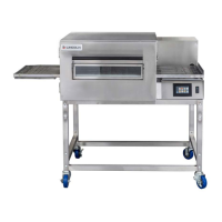
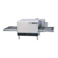
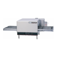
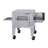
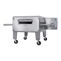
Related product manuals