This document describes the U-B30/B30Y Low Profile Scissor Lift, a hydraulic lifting device designed for vehicle maintenance and related services.
Function Description
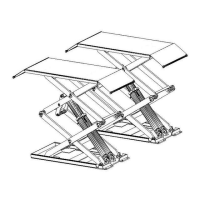
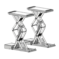
The U-B30/B30Y is a small platform, low-profile scissor lift capable of raising vehicles weighing up to 3000 kg. It is suitable for vehicle tests, maintenance, wheel alignment, and general automotive care. Its design makes it particularly well-suited for use in basements or on existing floors, as it does not require extensive construction or a ground pit.
The lift operates via an electrical hydraulic system. It features a hidden and thin scissor structure, which eliminates the need for ground holes and minimizes space occupation. The lift includes an independent control box with low-voltage control for enhanced security. Synchronization of the platforms is achieved through same-cubage hydraulic cylinders.
Safety is a key aspect of its design, incorporating double safety equipment: a hydraulic lock and a mechanical pawl. It also includes a safety valve and burst-proof equipment to protect against hydraulic failure and overloading, ensuring that the machine will not fall quickly even if an oil pipe bursts. High-quality hydraulic and electrical components from Italy, Germany, and Japan are utilized. In the event of a power cut, the lift supports manual lowering operations.
The basic structure consists of a machine basement (made of cement and concrete), a machine frame (the main structure and safety mechanism), and a control box (housing the hydraulic oil tank, hydraulic pump, valves, and electrical system). The frame itself is constructed from steel connecting rods, a main lifting platform, sliding boards, pneumatic double teeth, and a hydraulic oil tank.
The scissor lift is specifically designed for lifting vehicles. Any other use, such as washing/spraying, creating raised platforms for personnel, using it as a press, or as an elevator/lift jack for vehicle bodies or wheel changes, is unauthorized. The manufacturer disclaims responsibility for injuries or damages resulting from incorrect or unauthorized use.
Important Technical Specifications
Machine Type: U-B30 / U-B30Y
Drive: Electrical hydraulic
Max Lift Weight: 3000 kg
Main Machine Lift Height: 1850 mm
Platform Initial Height: 110 mm
Platform Length:
- U-B30: 1450 mm
- U-B30Y: 1450-2050 mm
Platform Width: 635 mm
Lifting Time: < 50 seconds
Descent Time: < 60 seconds
Whole Machine Length: 2040 mm
Whole Machine Width: 2020 mm
Whole Machine Weight: 850 kg
Power Supply: AC 400V or 230V ±5% 50Hz
Whole Machine Power: 2.2 KW
Hydraulic Oil: 12L (corresponds to wearable hydraulic oil)
Air Pressure: 6-8 kg/cm²
Working Temperature: 5-40°C
Working Humidity: 30-95%
Noise: < 76 dB
Installation Height: Height above sea level ≤ 1000M
Storage Temperature: -25°C to 55°C
Motor Specifications:
- Type: Y90L
- Max Power: 2.2 kW
- Max Voltage: AC 400 or 230V ±5%
- Max Electricity: 400V: 5A / 230V: 10A
- Max Frequency: 50Hz
- Poles: 4
- Speed: 1450 rpm/min
- Building Shape: B14
- Insulation Class: F
- Motor Direction: Clockwise (when connecting, refer to diagrams)
Pump Specifications:
- Type: P4.3 gear pump
- Max Flux: 4.3 cc/r
- Joint Type: Joint overfull valve
- Continuous Working Pressure: 210 bar
- Intermittent Working Pressure: 150-300 bar
- Hydraulic Oil Capacity: Inject 20 liters of wearable hydraulic oil into the oil tank.
Vehicle Compatibility:
The lift is suitable for vehicles with a total weight not exceeding 3000 kg and dimensions within the following limits:
- Length (A): 2000 mm (Min) to 4000 mm (Max)
- Width (B): 100 mm
- Height (C): 1900 mm
- Wheelbase (D): 900 mm
Usage Features
Installation Requirements:
- Installation must be performed by skilled and authorized personnel, following all instructions to prevent damage or injury.
- Minimum safety distance from walls and other equipment is 600 mm to allow for easy work and emergency access.
- The room must have a minimum height of 4000 mm.
- The floor must be perfectly level and sufficiently resistant (≥250 kg/cm², concrete thickness ≥150 mm). If the concrete thickness is less than 150mm, specific areas (2500x2500mm) must be irrigated to achieve ≥150mm thickness.
- All parts of the machine must be uniformly lit without reflected light or glare.
- The control box can be placed on either the left or right side of the lift.
- Power supply (400V or 230V 15A) and compressed air (Ø8x5mm) connections are required.
- Ground bolts should only be installed after the concrete has cured for 15 days to ensure solidity. Anchor bolts are installed using a percussion electric drill (16mm bit, 120mm deep).
Operation:
- Lifting: Press the "UP" button (SB1). The oil pump activates, sending hydraulic oil to the cylinders. The platform lifts, and the safety pawl is simultaneously lifted by the air loop. Releasing SB1 stops the pump, and the safety pawl engages the safety gear.
- Descent: Press the "DOWN" button (SB2). The safety pawl is lifted by the joint air loop, and the electromagnetic valve opens. The platform lifts for 2-3 seconds before lowering. Releasing SB2 stops the descent, and the safety pawl re-engages.
- Emergency Stop: Pressing the "emergency stop" button (SB0) locks the lift and cuts off all operation circuits.
Oil Make-up and Air Bleeding:
This process is crucial after installation and involves adding 18L of hydraulic oil (provided by the user) to the tank, ensuring it is clean and free of impurities.
- Open all three ball stop valves (G, H, I).
- Press "UP" (SB1) to lift platforms to their apex.
- Close valve G.
- Vent air by loosening screws on top of main oil cylinders, then press "UP" (SB1). Tighten screws once no air vents.
- Open valve G, close valves H and I, then press "DOWN" (SB2) to lower platforms.
- Repeat steps 2-5 for 4-5 times until no air is present.
Platforms Level Micro Adjustment:
- Press "UP" (SB1) to lift platforms about 100 mm.
- Close valve G, open valve H or I.
- Use "UP" and "DOWN" buttons to inch platforms to the same level.
- Close valve I or H, then open valve G.
Manual Lowering (Power Failure):
- Lift both safety pawls and secure them with a thin iron bar.
- Switch off the power button.
- Open the control box's back cover to access electromagnetic valve A.
- Loosen the manual oil loop stud at the end of the lowering electromagnetic valve core. The platform will begin to lower.
- Once lowered, tighten the manual oil loop stud.
Safety Precautions:
- Always work from specified stations.
- Never remove or deactivate safety guards or devices.
- Read all safety notices on the machine and in the manual.
- Prohibit persons from being in the danger zone during lifting/descent.
- Only enter the area beneath the vehicle when it is elevated, stationary, and mechanical safety devices are firmly engaged.
- Do not use the lift without protection devices or with them inhibited.
- Ensure correct vehicle positioning (Picture 7) and never exceed specified carrying capacity.
- Keep the area around the lift and platforms clean to prevent slipping from lubricant contamination.
- Avoid water, steam, solvents, or paint near the lift, especially the electrical control panel.
- Ensure adequate and uniform lighting.
- Always observe the lift during operations.
- Place rubber cushions under the vehicle chassis when lifting.
- Do not place anything on the lift-lowering area or movable parts.
- The photocell system ensures platforms are level; if not, the vehicle engine cannot be started during testing.
Maintenance Features
- Lubrication: All bearings and hinges must be lubricated weekly. Safety gear, upper and lower sliding blocks, and other movable parts require lubrication monthly.
- Hydraulic Oil Replacement: Hydraulic oil must be replaced annually. The oil level should always be kept at the upper limit. When replacing, lower the machine to its lowest position, drain the old oil, and filter the new hydraulic oil.
- Pneumatic Safety Equipment Check: Each team should regularly check the agility and reliability of the pneumatic safety equipment.
- Troubleshooting: The manual provides a detailed table of failure phenomena, their causes, and resolutions, covering issues such as motor non-operation, insufficient lifting, failure to lower, slow lowering, platform synchronization problems, and noisy operation. This includes checks for wire connections, contactor function, limit switches, oil levels, valve operation, air pressure, and lubrication.