UltraLink
®
Controller FTCU
Planning
The longer distance to disturbance, i.e. the longer straight
duct before the UltraLink
®
, the higher the measurement
accuracy will be. It is not recommended to mount the Ultra-
Link
®
so that the first flow sensor (* in the table on the next
page) is placed on an outer radius of a fitting. Never use an
UltraLink
®
on the outlet side of a duct fan. Place it on the
inlet side or in worst case use a flow conditioner if it must
be placed on the outlet side.
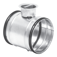
The sensor and the damper bodies can rotate relative to
each other. This means that the sensors can be optimally
positioned independently of the desired position of the
display and damper body. View table on next page for
directions on how to position the sensor body for optimal
performance.
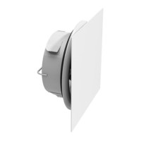
Mounting
Position the Controller so that the display is visible from
some direction. For future connections it is important that
the screws on the lid of the display can be removed. Make
sure the airflow arrow is pointing in the direction of the
airflow. Note the ID-number of the monitor. The ID can be
found on the label of the box the monitor was delivered in
or on the label on the monitor and are the three last num-
bers of the serial number.
Mount the Controller into the air duct system according to
the mounting instructions for Lindab Safe. Do not use the
flow sensors as handles when you mount the Controller
since they may break and changes in their positions might
influence the measurement accuracy. When the sensor
body is positioned accurately it should be connected with
screws to the damper body in the same way as when you
connect ducts and fittings.
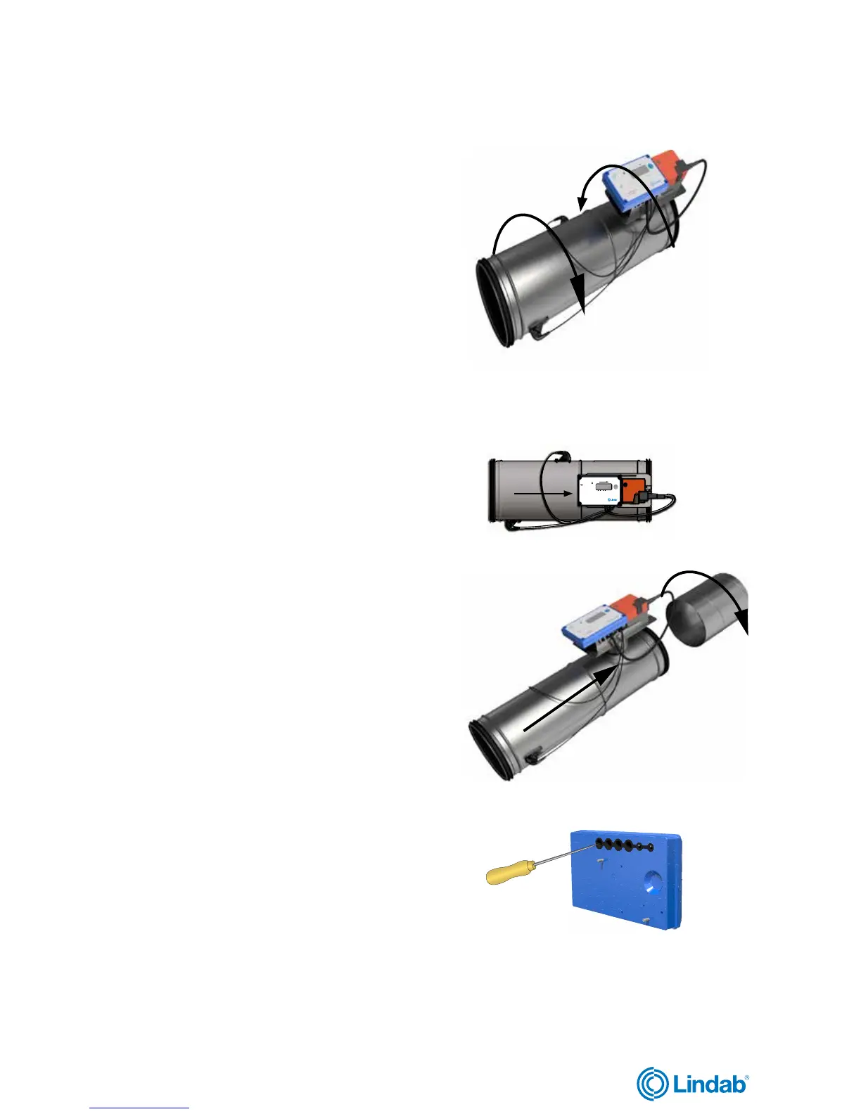
The Controller can be connected to a RTU (remote termi-
nal unit) via analog or RS485 communication (Modbus). To
be able to connect cords to the terminal board the rubber
cable grommet on the back of the display unit must be
punctured, preferably using an awl or something pointy to
ensure tightness to the environment. When the cords have
been connected they must be strain relieved. The cords
can be attached to the shelf by using cable ties that are
attached around cut outs in the shelf. You must under no
circumstances make any holes or connect anything with
screws to the sensor body since this will have an impact on
measurement accuracy.
 Loading...