Service Training
Section 6
Page 58
RP01 / Chapter 1
115 804 2401.1000
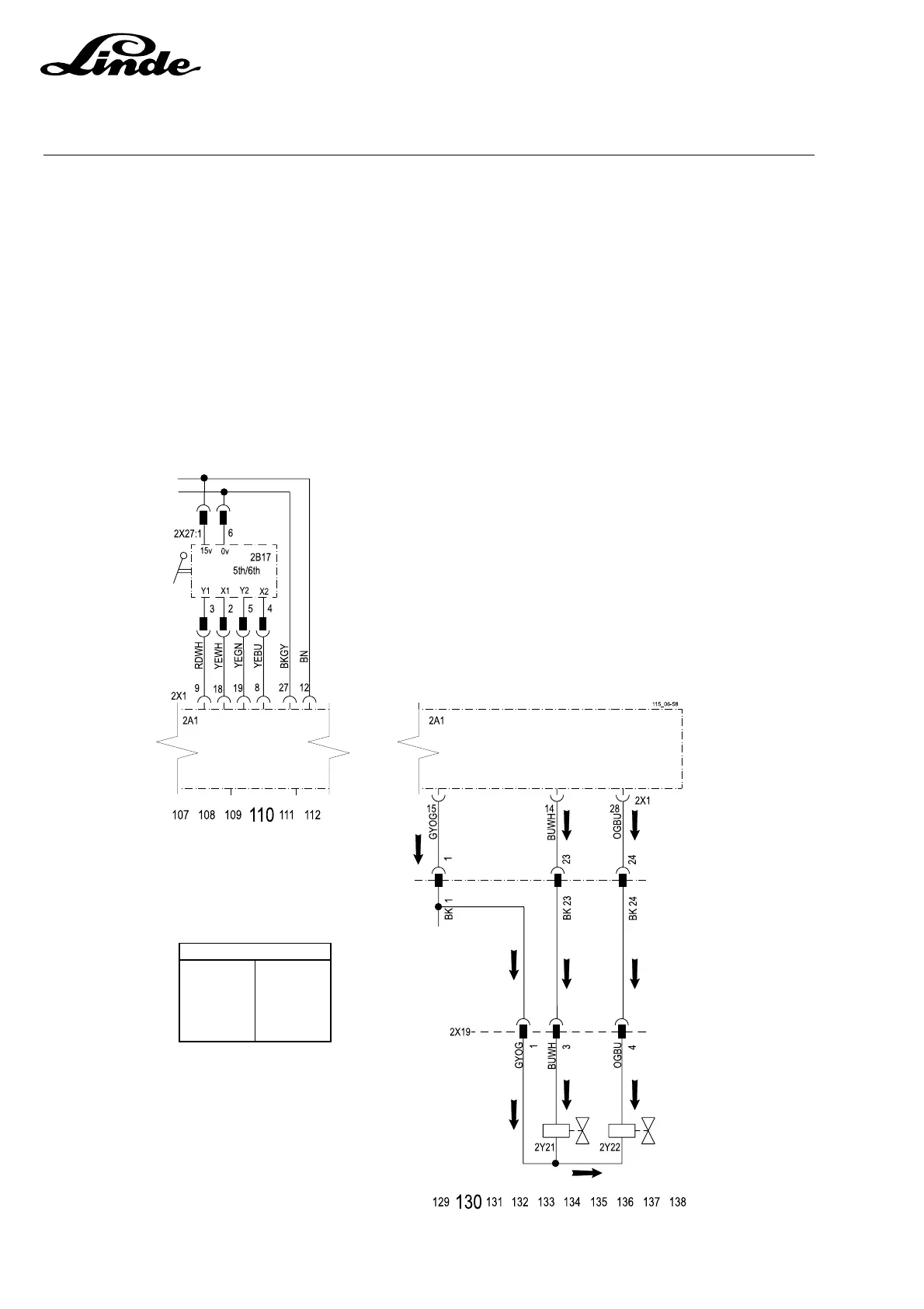
6.2.12.7 UPA JOYSTICK OPERATION FOR CLAMP ROTATE
CLAMP ROTATE FUNCTIONS 1 & 2
Joystick 2B17 controls clamp functions. Selecting Clamp option 1 or 2 provides variable voltages to 2X1:9
and 2X1:19. The module then provides a negative for either solenoid valve 2Y21 or 2Y22 from 2X1:14 or
2X1:22 At the same time the speed of the hydraulic motor controls operation speed.
5th and 6th inputs and outputs can be viewed in the following windows of the LLC diagnostic system.
Window 51: 5th and 6th hydraulic valve outputs and configuration detection at powerup.
Window 65: 5th hydraulic joystick inputs and motor outputs
Window 66: 6th hydraulic joystick inputs and motor outputs
48V+
BK = BLACK
BN = BROWN
OG = ORANGE
YE = YELLOW
RD = RED
GN = GREEN
BU = BLUE
VT = VIOLET
GY = GREY
WH = WHITE
COLOUR ABBREVIATIONS
 Loading...