Do you have a question about the Linde 350 Series and is the answer not in the manual?
Technical details of the VW ADG diesel engine, including capacity, output, and pressure specifications.
Details on fuel injection pump removal, installation, and timing adjustments.
Steps for cylinder head removal, installation, and related checks like compression.
Instructions for checking and testing the glow plug system for proper function.
Overview of the LHC system, fault detection, brake, and release valve functions.
Detailed diagram of the hydraulic system, including working hydraulics and engine components.
Guide to troubleshooting electrical and hydraulic systems using diagnostic tools.
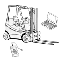
Procedures for diagnosing the electrical system using Linde test modules or PCs.
Instructions on operating the Linde Test Module for diagnostics.
Steps for PC-based diagnostics, including software installation and setup.
Details on navigating and using the Linde diagnostic program menus and functions.
Procedures for diagnosing hydraulic system faults and using test aids.
Provides a circuit diagram for hydraulic system diagnostics.
Troubleshooting methods for the power-assisted steering system.
Functional tests and troubleshooting procedures for the hydraulic brake system.
Step-by-step guide for adjusting accelerator and brake pedal strokes.
Procedures for adjusting the speed control mechanism.
Instructions for adjusting the engine speed sensor for correct readings.
Wiring diagram for the basic electrical system of the diesel version.
Wiring diagram for the basic electrical system of the LPG version.
Wiring diagrams for various optional equipment installations.
Shows the physical layout of electrical components and fuse boxes.
Details the functions and indicators of the main dashboard instrument panel.
Overall schematic diagram of the hydraulic system.
Procedures for sealing control valve slides and segments.
Instructions for setting pressure levels for working hydraulics.
General information and specifications for the LPG engine.
Details on the toothed belt system, including views and removal/installation.
Step-by-step guide for toothed belt maintenance procedures.
Procedures for removing, installing, and checking the cylinder head.
Overview of the electronic ignition system and its components.
Detailed description of the Bosch transistorised coil ignition system.
Guide for checking and adjusting the engine ignition timing.
Schematic and mounting instructions for the LPG system.
Diagram illustrating the LPG installation components and layout.
Details on mounting and adjusting the LPG mixer.
Procedures for adjusting idle and full load mixture for CO content.