RP01 / Chapter 1
115 804 2401.09.03
Page 65
Service Training
09.03
Section 6
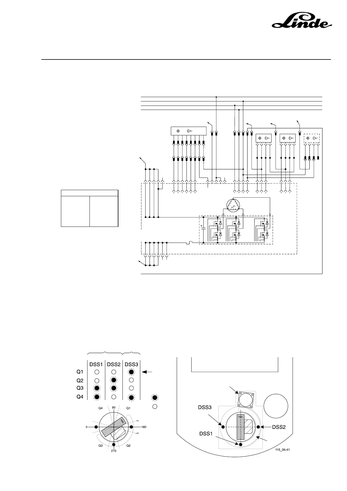
6.3.1 LES CIRCUIT DIAGRAM
BK = BLACK
BN = BROWN
OG = ORANGE
YE = YELLOW
RD = RED
GN = GREEN
BU = BLUE
VT = VIOLET
GY = GREY
WH = WHITE
COLOUR ABBREVIATIONS
3B1 Steering wheel encoder
3B2 Steering sensor 90°
3B3 Steering sensor 180°
3B4 Steering sensor 360°
3A1 LES controller
3M1 Power steering motor
6.3.2 STEERING SAFETY SENSORS
There are three inductive sensors that monitor the angle of the drive wheel. Two of these sensors (DSS1
and DSS2) are used by the steering controller to check against the absolute calculated angle that is used
for the steering indicator.
To steering
To
display
Position
shown
below
ON
OFF
(Sensor B)
(Sensor A) (Sensor C)
Steering
Motor/controller
(Sensor B)
(Sensor A)
(Sensor C)
Lift
motor
DSS2
+15V
16
15
4
6
5
4
6
5
NEG
PK
GY
YE
X10
7
8
172171 173
160
159158157156155154153152
170
169168167166165164163162161
180
179178177176175174
3M1
ASK ELECTRIC STEERING SYSTEM
3X1
3X1
3F1
KEY
24V
CAN HI
CAN LO
1
2
3
4
9
5
6
G/X49
3B3
8
1X11:23
3A1
181 182 183 184 185
6X1:4
9
BKRD
1
3X10B
BK
OGBU
4
2
3
3B4
3
2
WH
X48
BK1
BK3
7
11
BKRD
8
3
1
14
12
BN
5
BK
3X4B
BK2
10
10
2
4
3B1
7
BK4
BK5
3X4A
1
STEERING
WHEEL
TORQUE
CONTROL
BK7
NEG
D
C
B
A
+15
6
5
4
3
2
1
L/X50
3
4
1
BK6
5
6
3
2
NEG
DSS1
3
2
+15V
1X11:22
1
GN
BKGY
3B2
3X8 3X9 3X10
6
5
4
3
2
1
X7
16
15
14
7
13
12
11
8
13
3X1
7
1X11:28
BK8
8
6
1
BK
4
2
3X15
9
WH
BN
111444333222
BN
BN
BN
BK
BK
BK
BU
BU
BU
WH
WH
WH
115_06-40
 Loading...